
Page 169 - Radar Technology Encyclopedia
P. 169
159 ECM, deception ECM, range measurement
the seeker to home on the jammer-illuminated patch on the Offboard ECM systems are designed to be used remotely
earth’s surface rather than on the jammer itself. from the defended platform (e.g., airborne or naval plat-
Both blinking and terrain bounce techniques can be forms). The main representatives of this systems are decoys
implemented in either repeater jammer or noise jammer con- (active and passive) and chaff. SAL
figurations. (See also JAMMING, deception.) PCH, SAL Ref.: Neri (1991), pp. 399–411.
Ref.: Schleher (1986), pp. 138, 145–160; Skolnik (1990), p. 9.5.
Onboard ECM systems are ECM devices within the
Downlink ECM is used against satellites, aircraft, and mis- defended platform. Typically, they are active systems: noise
sile-borne radars that have separate, onboard systems to and deception jammers. Sometimes various means for RCS
“downlink” target information or other radar sensor data, reduction are classified as passive ingredients of onboard
such as platform position and radar mapping data, from the ECM systems. SAL
radar acquisition platform to a ground radar or data process- Ref.: Neri (1991), pp. 338–364.
ing center. Downlink ECM is directed at disrupting this line Passive ECM refers to electronic countermeasures involving
of communication. devices reflecting electromagnetic energy in such a manner
In the interest of efficiency as well as security, most of that the reradiated signal competes with true target return to
the waveforms used by downlink transmitters are modulated conceal real reflection. A typical example of passive ECM is
in either time, frequency, phase, amplitude, or combinations chaff. SAL
thereof. Encryption algorithms may be superimposed for
Ref.: Barton (1991), p. 12-8; Chrzanowski (1990), p. 8.
added security. In the absence of detailed knowledge of the
Range-measurement ECM provides interfering signals, the
downlinked signal coding, attempts to interfere with the
main goal of which is disrupting the measurement of time of
downlink are mostly restricted to the use of stand-off noise
arrival to determine target range. Typically, it may be imple-
jamming.
mented in two ways. First is to cover or suppress echo return
Downlink jamming is made more difficult still, due to the
before it can be detected in radar receiver. Noise jamming is
one-way transmission path of the downlink, and the usually
an appropriate technique for this purpose; only the high radi-
high power transmitters employed by downlink systems.
ated power is required, especially if frequency agility is
Downlink transmission systems generally employ fairly wide
employed in victim radar. The second is to confuse a radar as
beamwidth antennas, but even coarse directivity can pose sig-
to the true location of the target. This can be implemented by
nificant problems for a noise jammer, forcing it, in many cir-
use of deception jamming. In this case false targets (passive
cumstances (e.g., a missile downlink) to jam through the
decoys) presenting many radar blips with different ranges and
downlink antenna sidelobes. Yet another complication for the
range-gate pull-off are the effective measures.
missile downlink jammer occurs when the downlink is used
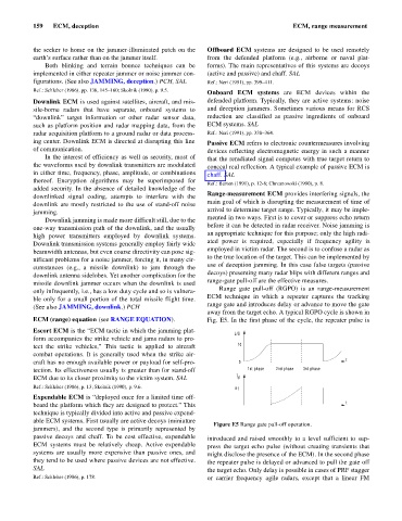
Range gate pull-off (RGPO) is an range-measurement
only infrequently, i.e., has a low duty cycle and so is vulnera-
ECM technique in which a repeater captures the tracking
ble only for a small portion of the total missile flight time.
range gate and introduces delay or advance to move the gate
(See also JAMMING, downlink.) PCH
away from the target echo. A typical RGPO cycle is shown in
ECM (range) equation (see RANGE EQUATION). Fig. E5. In the first phase of the cycle, the repeater pulse is
Escort ECM is the “ECM tactic in which the jamming plat-
J/S
form accompanies the strike vehicle and jams radars to pro-
tect the strike vehicles,” This tactic is applied to aircraft 10
combat operations. It is generally used when the strike air-
t
craft has no enough available power or payload for self-pro- 0
tection. Its effectiveness usually is greater than for stand-off 1st phase 2nd phase 3rd phase
t
ECM due to its closer proximity to the victim system. SAL d
Ref.: Schleher (1986), p. 13; Skolnik (1990), p. 9.6. t D
Expendable ECM is “deployed once for a limited time off-
t
board the platform which they are designed to protect.” This
technique is typically divided into active and passive expend-
able ECM systems. First usually are active decoys (miniature
Figure E5 Range gate pull-off operation.
jammers), and the second type is primarily represented by
passive decoys and chaff. To be cost effective, expendable introduced and raised smoothly to a level sufficient to sup-
ECM systems must be relatively cheap. Active expendable press the target echo pulse (without creating transients that
systems are usually more expensive than passive ones, and might disclose the presence of the ECM). In the second phase
they tend to be used where passive devices are not effective. the repeater pulse is delayed or advanced to pull the gate off
SAL the target echo. Only delay is possible in cases of PRF stagger
Ref.: Schleher (1986), p. 178. or carrier frequency agile radars, except that a linear FM