
Page 168 - Radar Technology Encyclopedia
P. 168
ECM, cross-polarization ECM, deception 158
of cross-polarized components, depending on the radome antenna sidelobes, thus making discrimination of the true tar-
design. get more difficult or impossible. Angle deception can also be
Counter-countermeasures to cross-polarization jamming directed to attack the angle-tracking capability of a tracking
include the use of polarization screens to block signals with radar or radar homing missile seeker. In this role angle decep-
undesired polarizations. A more expensive and complex tion jamming is usually an integral component of a general
option entails the use of antennas capable of receiving multi- class of DECM techniques used by self-screening jammers
ple polarizations, perhaps in conjunction with one or more (SSJ) to protect the host platform (e.g., an aircraft, ship, or
separate receiver and signal-processing channel. missile) from engagement by an air-defense system. Most
To be effective, even against single-polarization radars, angle deception techniques are implemented via a repeater
cross-polarization jammers must realize high J/S ratios while jammer, which retransmits an amplified version of the victim
accurately maintaining jammer-to-radar signal polarization radar’s signal that has been modulated such that the angle
orthogonality (typically to within plus-or-minus 5°). If these data recovered by the victim radar no longer represents the
conditions are not met, the jammer signal can become the true target’s angular position relative to the radar.
equivalent of a target-borne radar beacon, making the jammer To be effective, an angle deception jamming technique
platform highly susceptible to engagement by radar homing must be tailored to the particular way in which the victim
missiles. radar derives target angle information. Track-while-scan
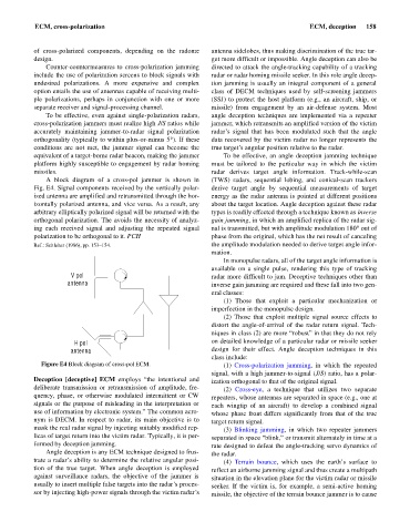
A block diagram of a cross-pol jammer is shown in (TWS) radars, sequential lobing, and conical-scan trackers
Fig. E4. Signal components received by the vertically polar- derive target angle by sequential measurements of target
ized antenna are amplified and retransmitted through the hor- energy as the radar antenna is pointed at different positions
izontally polarized antenna, and vice versa. As a result, any about the target location. Angle deception against these radar
arbitrary elliptically polarized signal will be returned with the types is readily effected through a technique known as inverse
orthogonal polarization. The avoids the necessity of analyz- gain jamming, in which an amplified replica of the radar sig-
ing each received signal and adjusting the repeated signal nal is transmitted, but with amplitude modulation 180° out of
polarization to be orthogonal to it. PCH phase from the original, which has the net result of canceling
Ref.: Schleher (1986), pp. 153–154. the amplitude modulation needed to derive target angle infor-
mation.
In monopulse radars, all of the target angle information is
available on a single pulse, rendering this type of tracking
V pol radar more difficult to jam. Deceptive techniques other than
antenna inverse gain jamming are required and these fall into two gen-
eral classes:
(1) Those that exploit a particular mechanization or
imperfection in the monopulse design.
(2) Those that exploit multiple signal source effects to
distort the angle-of-arrival of the radar return signal. Tech-
niques in class (2) are more “robust” in that they do not rely
H pol on detailed knowledge of a particular radar or missile seeker
antenna design for their effect. Angle deception techniques in this
class include:
Figure E4 Block diagram of cross-pol ECM. (1) Cross-polarization jamming, in which the repeated
signal, with a high jammer-to-signal (J/S) ratio, has a polar-
Deception [deceptive] ECM employs “the intentional and ization orthogonal to that of the original signal.
deliberate transmission or retransmission of amplitude, fre- (2) Cross-eye, a technique that utilizes two separate
quency, phase, or otherwise modulated intermittent or CW repeaters, whose antennas are separated in space (e.g., one at
signals or the purpose of misleading in the interpretation or each wingtip of an aircraft) to develop a combined signal
use of information by electronic system.” The common acro- whose phase front differs significantly from that of the true
nym is DECM. In respect to radar, its main objective is to target return signal.
mask the real radar signal by injecting suitably modified rep- (3) Blinking jamming, in which two repeater jammers
licas of target return into the victim radar. Typically, it is per- separated in space “blink,” or transmit alternately in time at a
formed by deception jamming. rate designed to defeat the angle-tracking servo dynamics of
Angle deception is any ECM technique designed to frus- the radar.
trate a radar’s ability to determine the relative angular posi- (4) Terrain bounce, which uses the earth’s surface to
tion of the true target. When angle deception is employed reflect an airborne jamming signal and thus create a multipath
against surveillance radars, the objective of the jammer is situation in the elevation plane for the victim radar or missile
usually to insert multiple false targets into the radar’s proces- seeker. If the victim is, for example, a semi-active homing
sor by injecting high-power signals through the victim radar’s missile, the objective of the terrain bounce jammer is to cause