
Page 29 - Reciprocating Compressors Operation Maintenance
P. 29
1 6 Reciprocating Compressors: Operation and Maintenance
Suction Pressure
*M ~~
Volume
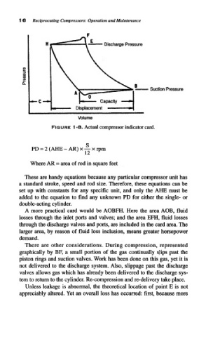
FIGURE I -8. Actual compressor indicator card.
PD = 2 (AHE - AR) x — x rpm
Where AR = area of rod in square feet
These are handy equations because any particular compressor unit has
a standard stroke, speed and rod size. Therefore, these equations can be
set up with constants for any specific unit, and only the AHE must be
added to the equation to find any unknown PD for either the single- or
double-acting cylinder.
A more practical card would be AOBFH. Here the area AOB, fluid
losses through the inlet ports and valves; and the area EFH, fluid losses
through the discharge valves and ports, are included in the card area. The
larger area, by reason of fluid loss inclusion, means greater horsepower
demand.
There are other considerations. During compression, represented
graphically by BF, a small portion of the gas continually sjiips past the
piston rings and suction valves. Work has been done on this gas, yet it is
not delivered to the discharge system. Also, slippage past the discharge
valves allows gas which has already been delivered to the discharge sys-
tem to return to the cylinder. Re-compression and re-delivery take place.
Unless leakage is abnormal, the theoretical location of point E is not
appreciably altered. Yet an overall loss has occurred: first, because more