
Page 217 - Refining Biomass Residues for Sustainable Energy and Bioproducts
P. 217
Generation of bioenergy from industrial waste using microbial fuel cell technology 187
8.5.1 Microbial fuel cell configurations and designs
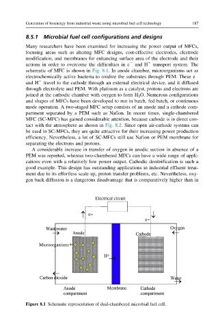
Many researchers have been examined for increasing the power output of MFCs,
focusing areas such as altering MFC designs, cost-effective electrodes, electrode
modification, and membranes for enhancing surface area of the electrode and their
actions in order to overcome the difficulties in e 2 and H 1 transport system. The
schematic of MFC is shown in Fig. 8.1. In anode chamber, microorganisms act as
electrochemically active bacteria to oxidize the substrates through PEM. These e 2
1
and H travel to the cathode through an external electrical device, and it diffused
through electrolyte and PEM. With platinum as a catalyst, protons and electrons are
joined at the cathodic chamber with oxygen to form H 2 O. Numerous configurations
and shapes of MFCs have been developed to run in batch, fed-batch, or continuous
mode operation. A two-staged MFC setup consists of an anode and a cathode com-
partment separated by a PEM such as Nafion. In recent times, single-chambered
MFC (SC-MFC) has gained considerable attention, because cathode is in direct con-
tact with the atmosphere as shown in Fig. 8.2. Since open air-cathode systems can
be used in SC-MFCs, they are quite attractive for their increasing power production
efficiency. Nevertheless, a lot of SC-MFCs still use Nafion or PEM membrane for
separating the electrons and protons.
A considerable increase in transfer of oxygen in anodic section in absence of a
PEM was reported, whereas two-chambered MFCs can have a wide range of appli-
cations even with a relatively low power output. Cathodic denitrification is such a
good example. This design has outstanding applications in industrial effluent treat-
ment due to its effortless scale-up, proton transfer problems, etc. Nevertheless, oxy-
gen back diffusion is a dangerous disadvantage that is comparatively higher than in
Figure 8.1 Schematic representation of dual-chambered microbial fuel cell.