
Page 228 - Robot Builder's Bonanza
P. 228
PREVENTING REVERSE BATTERY POLARITY 197
Preventing Reverse Battery Polarity
At all costs, avoid reversing the connection of your batteries when you plug them into your
robot. At best, your bot won’t function; at worst (more likely), you’ll instantaneously blow out
some or all of the electronics. There are two general choices: mechanical interlock and elec-
tronic polarity protection.
MECHANICAL POLARIZED CONNECTIONS
You can reduce and even eliminate the possibility of hooking up your batteries the wrong way
simply by using a “polarized” connector. A coaxial barrel connector used with many low- voltage
DC wall transformers is by far the simplest and most common. You need a mating socket on
your circuit or breadboard.
Barrel plugs and sockets come in different diameters, sized in millimeters. You need to
make sure the plug on your battery pack is the right size. The Arduino microcontroller boards,
for example, use a 2.1mm barrel plug. Many sellers of the Arduino offer battery packs and
9- volt battery connectors with the 2.1mm barrel plug already on them.
The center connector on the plug can be + or . When soldering a barrel plug to your
battery pack (or using a wall transformer with a barrel plug already on it), be absolutely sure
to observe the correct polarity! Center positive is the most common, but never assume that’s
the case. Always double- check.
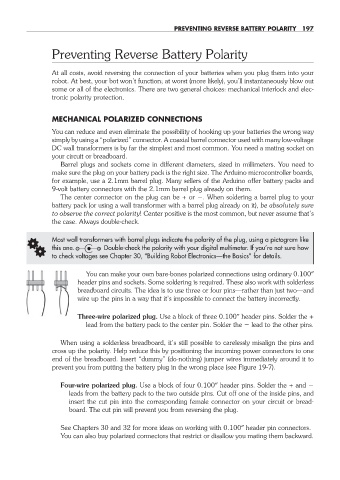
G Most wall transformers with barrel plugs indicate the polarity of the plug, using a pictogram like
this one. Double- check the polarity with your digital multimeter. If you’re not sure how
to check voltages see Chapter 30, “Building Robot Electronics— the Basics” for details.
You can make your own bare- bones polarized connections using ordinary 0.100″
header pins and sockets. Some soldering is required. These also work with solderless
breadboard circuits. The idea is to use three or four pins— rather than just two— and
wire up the pins in a way that it’s impossible to connect the battery incorrectly.
Three- wire polarized plug. Use a block of three 0.100″ header pins. Solder the +
lead from the battery pack to the center pin. Solder the lead to the other pins.
When using a solderless breadboard, it’s still possible to carelessly misalign the pins and
cross up the polarity. Help reduce this by positioning the incoming power connectors to one
end of the breadboard. Insert “dummy” (do- nothing) jumper wires immediately around it to
prevent you from putting the battery plug in the wrong place (see Figure 19- 7).
Four- wire polarized plug. Use a block of four 0.100″ header pins. Solder the + and
leads from the battery pack to the two outside pins. Cut off one of the inside pins, and
insert the cut pin into the corresponding female connector on your circuit or bread-
board. The cut pin will prevent you from reversing the plug.
See Chapters 30 and 32 for more ideas on working with 0.100″ header pin connectors.
You can also buy polarized connectors that restrict or disallow you mating them backward.
19-chapter-19.indd 197 4/21/11 11:49 AM