
Page 295 - Robot Builder's Bonanza
P. 295
264 USING SERVO MOTORS
G These steps are virtually the same for several other popular low- cost servos, including the
Futaba S- 148, and the S03 series of servos from GWS.
STEPS FOR MODIFYING A FUTABA S3003 SERVO
The Futaba S3003 is a low- cost alternative to servos with metal bushing or ball bearings. As
with many servos of its type, it doesn’t use a retained clip for the potentiometer. You need to
drill out the bottom of the gear so that the gear will no longer engage with the potentiometer.
1. Follow steps 1 through 6, above.
2. Using a spare servo horn (the larger, the better), attach the horn to the output gear
using the mounting screw provided with the servo.
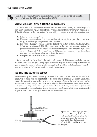
3. For steps 7 though 9, instead, carefully drill out the bottom of the output gear with a
3/16″ (or thereabouts) drill bit. Remove as much of the plastic as necessary so that the
potentiometer shaft will not engage the bottom of the gear. Use a drill press if you have
one. See Figure 23- 9. If you don’t have a drill press, get someone to hold the output
gear (see the note below) while you drill out the spline.
4. Complete the remainder of the steps above.
When you drill out the spline in the bottom of the gear, hold the gear steady by clasping
the servo horn— not the gear— using a pair of heavy- duty pliers. Do not clamp by the shaft or
gear face, as this could wreck the plastic and you’ll end up with a badly functioning servo. Be
sure not to ream or drill out too much, or you’ll ruin the gear.
TESTING THE MODIFIED SERVO
After reassembly but before connecting the servo to a control circuit, you’ll want to test your
handiwork to make sure the output shaft of the servo rotates smoothly. Do this by attaching a
control disc or control horn to the output shaft of the servo. Slowly and carefully rotate the disc
or horn and note any snags. Don’t spin too quickly, as this will put undue stress on the gears.
If you notice any binding while you’re turning the disc or horn, it could mean you didn’t
remove enough of the mechanical stop on the output gear. Disassemble the servo just enough
to gain access to the output gear and clip or file off some more.
Drill out slot for
potentiometer shaft from
bottom of gear
Figure 23- 9 If modifying a servo
where the slot for the potentiometer
Gear shaft is molded into the plastic of the
output gear, attach the gear to a servo
horn and drill out the bottom with a
Servo disc
3/16″ drill bit. Hold the servo horn
with pliers.
23-chapter-23.indd 264 4/21/11 11:51 AM