
Page 307 - Robot Builder's Bonanza
P. 307
276 MOUNTING MOTORS AND WHEELS
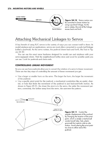
Figure 24- 10 Rotary motion can
be converted to linear motion by
using a pushrod linkage. As the
servo rotates, the end of the linkage
moves back and forth.
Attaching Mechanical Linkages to Servos
A key benefit of using R/C servos is the variety of ways you can connect stuff to them. In
model airplane and car applications, servos are most often connected to a push/pull linkage
(called a pushrod). As the servo rotates, the pushrod draws back and forth, like that in Fig-
ure 24- 10.
You can use the exact same hardware designed for model cars and airplanes with your
servo- equipped robots. Visit the neighborhood hobby store and scout for possible parts you
can use. Look for pushrods and clevis ends.
CONTROLLING LINEAR MOVEMENT
So you can see how pushrods allow you to convert the rotation of a servo to linear movement.
There are two key ways of controlling the amount of linear movement you get:
• Use a larger or smaller horn on the servo. The larger the horn, the larger the movement
of the pushrod.
• Use a specific pivot point for the pushrod, a mechanical constriction like an eyelet, chan-
nel, or hole that limits the movement of the pushrod to just back- and- forth motion. As
shown in Figure 24- 11, the closer the pivot is to the servo, the wider the movement pat-
tern; conversely, the farther away from the servo, the narrower the pattern.
Pivot point
Narrow pattern
Large hub disc
attached to servo
Figure 24- 11 Control the
angular displacement of the pushrod
by changing the location of the pivot
Pivot point point, which is simply a mechanical
conduit (small tube, hole, plastic
grommet) that restricts side- to- side
motion. Avoid placing the pivot point
too close to either end of the
Wide pattern pushrod.
24-chapter-24.indd 276 4/21/11 11:51 AM