
Page 332 - Robot Builder's Bonanza
P. 332
BASIC DESIGN PRINCIPLES OF ROLLING ROBOTS 301
Turns within this circle
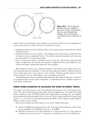
Figure 26- 3 The turning circle
describes the area occupied by a
robot when it makes a spinning turn.
Given the same- diameter base,
wheels on the inside of the base
circumference have a smaller turning
Equal size bases circle.
steered robot: by reversing the motors relative to one another (hard turn) or by stopping one
motor and activating the other (soft turn). In both kinds of turns,
• Inadequate traction causes the wheels to slip, so it’s anyone’s guess where the robot will be
heading afterward.
• Excessive traction can cause “chatter”—the wheels grip the road surface so well, they have
to bounce in order to negotiate the turn. The effect is most pronounced in soft turns and
is compounded in 4- and 6- wheel designs.
• Four or more driven wheels, mounted in sets on each side, will function much like tank
tracks. In tight turns, the wheels will experience significant friction and skidding. If you
choose this design, position the wheel sets closer together.
Most wheels for robotics use a rubber tire material. The softness of the rubber and its sur-
face help determine its compliance. A very soft and mushy tire material— like that found on
some model racing cars— may cause too much traction, hindering proper steering. A very
hard tire material, such as a hard plastic, may not provide enough grip.
The effectiveness of any tire material is determined by the surface it rolls over. A hard tire
on a hardwood floor can be a bad combination; a moderately soft tire on Berber carpet is a
much better combination.
USING WHEEL DIAMETER TO CALCULATE THE SPEED OF ROBOT TRAVEL
The speed of the drive motors is one of two elements that determine the travel speed of your
robot. The other is the diameter of the wheels. For most applications, the speed of the drive
motors should be under 130 RPM (under load). With wheels of average size, the resultant
travel speed will be approximately 4 feet per second. That’s actually pretty fast. A better travel
speed is 1 to 2 feet per second (approximately 65 RPM), which requires smaller- diameter
wheels, a slower motor, or both.
How do you calculate the travel speed of your robot? Follow these steps:
1. Divide the RPM speed of the motor by 60. The result is the revolutions of the motor
per second (RPS). A 100 RPM motor runs at 1.66 RPS.
2. Multiply the diameter of the drive wheel by pi, or approximately 3.14. This yields the
circumference of the wheel. A 7″ wheel has a circumference of about 21.98 inches.
26-chapter-26.indd 301 4/21/11 11:52 AM