
Page 413 - Robot Builder's Bonanza
P. 413
382 COMMON ELECTRONIC COMPONENTS FOR ROBOTICS
Ground Resistor
Battery or (also called Unconnected Connected
power source common) wires wires
Switch
Light
6v emitting
battery diode
Analog Digital Digital
input or output output input
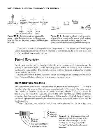
Figure 31- 1 Basic schematic symbols used for Figure 31- 2 Example of a basic circuit, shown in
wiring circuits. There are variations of those shown schematic form. It consists of a battery, switch, resistor,
here, but these are the wiring symbols used throughout and light- emitting diode. In many instances, the
this book. symbols are self- explanatory or pictorially descriptive.
There are hundreds of different electronic components, but only a small handful see regular
use in electronic circuits for robotics. So instead of listing them all, I’ll cover only those that
you’re most likely to encounter and use.
Fixed Resistors
Besides wire, resistors are the most basic of all electronic components. A resistor opposes the
passing of current through it. It’s like squeezing down a rubber hose to keep water from flow-
ing through. Fixed resistors (there are also variable resistors, discussed next) apply a predeter-
mined resistance to a circuit.
By using resistors of different values in a circuit, different parts get varying amounts of cur-
rent. The careful balance of current is what makes the circuit work.
HOW RESISTORS ARE RATED
The standard unit of value of a resistor is the ohm, represented by the symbol . The higher
the ohm value, the more resistance the component provides to the circuit. The value on most
fixed resistors is identified by color- coded bands, as shown in Figure 31- 3 (you can’t see the
colors here, but you get the idea). The color coding starts near the edge of the resistor and
comprises four, five, and sometimes six bands of different colors. Most off- the- shelf resistors
for amateur projects use standard four- band color coding. They’re the easiest to find, and the
least expensive.
To read the value, start with the band closest to the edge and decode the colors using
Resistor
schematic
symbols Figure 31- 3 Component outline and
schematic symbols for a resistor. In this
Tolerance
Multiplier book the hollow rectangle is used for
resistors, but you may encounter the
2nd Significant figure
“sawtooth” symbol used in schematics
1st Significant figure elsewhere.
31-chapter-31.indd 382 4/21/11 11:56 AM