
Page 416 - Robot Builder's Bonanza
P. 416
FIXED RESISTORS 385
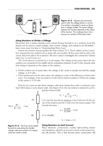
Figure 31- 5 Resistors are commonly
used to alter the voltage levels in a circuit.
Two resistors connected in series as shown
form a voltage divider. The actual voltage
between the resistors depends on the values
of the resistors. The readings shown here
assume two resistors of the same value.
Using Resistors to Divide a Voltage
Remember that a resistor literally resists current flowing through it. In a working circuit this
feature can be used to control voltage, since current, voltage, and resistance are all related—
learn more about this later in “Understanding Ohm’s Law.”
Picture two resistors strung together like that in Figure 31- 5. This is called a series connec-
tion, because the two resistors are in series with one another. (If they were side by side in the
circuit, they’d be said to be in parallel. We don’t need to investigate this connection scheme
right now, so we’ll move on.)
The circuit shown is powered by a 5- volt supply. The voltage at the point where the two
resistors are connected in the middle will be somewhere between 0 and 5 volts. Exactly what
that voltage is depends on the values of the resistors.
• If both resistors are of equal value, the voltage at the center is exactly one- half the supply
voltage, or 2.5 volts.
• If the resistors are not the same value, the voltage is a ratio of the difference of their resis-
tance. For example, if the top resistor is 5 k and the bottom resistor is 10 k , the voltage
at the center is 3.33 volts.
How do you come up with these voltages, other than testing them with a multimeter each
time? All it takes is some simple math. See Figure 31- 6; the top resistor is referred to as R1,
and the bottom is R2.
R 2
V in ———— = V out
R 1 + R 2
Let’s test this formula by plugging in the 5 k and 10 k val-
ues of the resistors and the 5 volts from the power supply. The
formula becomes:
10,000
5 ———— = 3.33
15,000
or, to simplify:
5 0.66 = 3.3
Figure 31- 6 The basic (and simple) Using Resistors to Limit Current
formula for calculating the divided Many electronic components, notably light- emitting diodes
voltage, when two resistors of unequal and transistors, will suck up as much current as the power sup-
value are wired in series. ply will provide. This is bad because these components will
31-chapter-31.indd 385 4/21/11 11:56 AM