
Page 420 - Robot Builder's Bonanza
P. 420
POTENTIOMETERS 389
Rotary (dial)
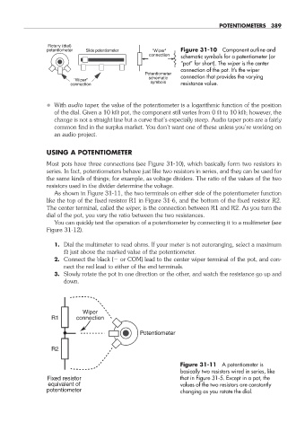
potentiometer Slide potentiometer "Wiper" Figure 31- 10 Component outline and
connection schematic symbols for a potentiometer (or
“pot” for short). The wiper is the center
connection of the pot. It’s the wiper
Potentiometer
schematic connection that provides the varying
"Wiper"
connection symbols resistance value.
• With audio taper, the value of the potentiometer is a logarithmic function of the position
of the dial. Given a 10 k pot, the component still varies from 0 to 10 k ; however, the
change is not a straight line but a curve that’s especially steep. Audio taper pots are a fairly
common find in the surplus market. You don’t want one of these unless you’re working on
an audio project.
USING A POTENTIOMETER
Most pots have three connections (see Figure 31- 10), which basically form two resistors in
series. In fact, potentiometers behave just like two resistors in series, and they can be used for
the same kinds of things; for example, as voltage dividers. The ratio of the values of the two
resistors used in the divider determine the voltage.
As shown in Figure 31- 11, the two terminals on either side of the potentiometer function
like the top of the fixed resistor R1 in Figure 31- 6, and the bottom of the fixed resistor R2.
The center terminal, called the wiper, is the connection between R1 and R2. As you turn the
dial of the pot, you vary the ratio between the two resistances.
You can quickly test the operation of a potentiometer by connecting it to a multimeter (see
Figure 31- 12).
1. Dial the multimeter to read ohms. If your meter is not autoranging, select a maximum
just above the marked value of the potentiometer.
2. Connect the black ( or COM) lead to the center wiper terminal of the pot, and con-
nect the red lead to either of the end terminals.
3. Slowly rotate the pot in one direction or the other, and watch the resistance go up and
down.
Wiper
R1 connection
Potentiometer
R2
Figure 31- 11 A potentiometer is
basically two resistors wired in series, like
Fixed resistor that in Figure 31- 5. Except in a pot, the
equivalent of values of the two resistors are constantly
potentiometer changing as you rotate the dial.
31-chapter-31.indd 389 4/21/11 11:56 AM