
Page 419 - Robot Builder's Bonanza
P. 419
388 COMMON ELECTRONIC COMPONENTS FOR ROBOTICS
refer to Appendix D, “Electronic Reference,” for a brief discussion of using the Ohm’s law
wheel. For now, though, we only need to apply one of the 12 formulas of the wheel.
Let’s return to the example of selecting a resistor to limit current to an LED. The formula
to calculate power is very simple:
V I = W
• V = voltage through the LED. This includes the voltage drop through the LED; from the
previous example this voltage is 3.0.
• I = current to the LED. From the previous example this is 15 mA, or .015.
• W is the power dissipation, in watts. The resistor needs to be rated to dissipate at least this
amount of power.
Substituting the actual values, you get
3.0 0.015 = 0.045
The answer is in whole watts; 0.045 is less than 1/20 of a watt, so the standard 1/8- watt
resistor is more than enough.
Potentiometers
Potentiometers are technically variable resistors. They let you “dial in” a specific resistance.
The actual range of resistance is determined by the upward value of the potentiometer, and
this upward value is how the potentiometer is marked. As with fixed resistors, the values are
in ohms. For example, a 50 k potentiometer will let you dial in any
resistance from 0 ohms to 50,000 ohms.
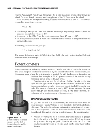
Potentiometers (or pots for short) are of either the dial or the slide
type. The dial type shown in Figure 31- 9 is the most familiar and is used
in such applications as radio volume and electric blanket thermostat con-
trols. The rotation of the dial is nearly 360°. In one extreme, the resis-
tance through the potentiometer is zero; in the other extreme, the
resistance is the maximum value of the component.
LINEAR OR AUDIO TAPER
As you turn the dial of a potentiometer, the resistance varies from the
lower extreme— usually 0 ohms, or very close to it— to the indicated value
of the pot. The scale of the change is dependent on the internal construc-
tion of the component. There are two scales: linear and audio (also called
logarithmic). The scale is referred to as the taper of the potentiometer.
Figure 31- 9 A • With linear taper, the most common, the value changes in propor-
potentiometer is a variable tion to the setting of the dial. For example, with a 10 k pot, turning
resistor. Turn the shaft of it a quarter of the way will yield 1/4 of the full scale, or 2.5 k . For
the potentiometer and its nearly everything you do in robotics you’ll want a linear taper poten-
resistance changes. tiometer.
31-chapter-31.indd 388 4/21/11 11:56 AM