
Page 246 -
P. 246
4.5 Digital Robot Control 229
where r k is the reference command and w k is the controller input, composed
-1
generally of the tracking error and the plant measured output. Note that z is
interpreted in the time domain as a unit delay of T seconds. The controller
output v k is passed through a hold device to generate the continuous plant
control input u(t).
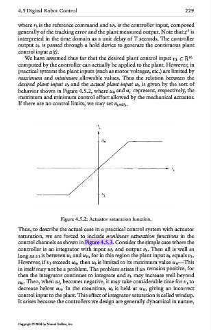
We have assumed thus far that the desired plant control input
computed by the controller can actually be applied to the plant. However, in
practical systems the plant inputs (such as motor voltages, etc.) are limited by
maximum and minimum allowable values. Thus the relation between the
desired plant input v k and the actual plant input u k is given by the sort of
behavior shown in Figure 4.5.2, where u H and u L represent, respectively, the
maximum and minimum control effort allowed by the mechanical actuator.
If there are no control limits, we may set u k =v k .
Figure 4.5.2: Actuator saturation function.
Thus, to describe the actual case in a practical control system with actuator
saturation, we are forced to include nonlinear saturation functions in the
control channels as shown in Figure 4.5.3. Consider the simple case where the
controller is an integrator with input w k and output v k. Then all is well as
long as v k is between u L and u H, for in this region the plant input u k equals v k.
However, if v k exceeds u H, then u k is limited to its maximum value u H—This
in itself may not be a problem. The problem arises if w k remains positive, for
then the integrator continues to integrate and v k may increase well beyond
u H. Then, when w k becomes negative, it may take considerable time for v k to
decrease below u H. In the meantime, u k is held at u H, giving an incorrect
control input to the plant. This effect of integrator saturation is called windup.
It arises because the controllers we design are generally dynamical in nature,
Copyright © 2004 by Marcel Dekker, Inc.