
Page 152 - Robot Builders Source Book - Gordon McComb
P. 152
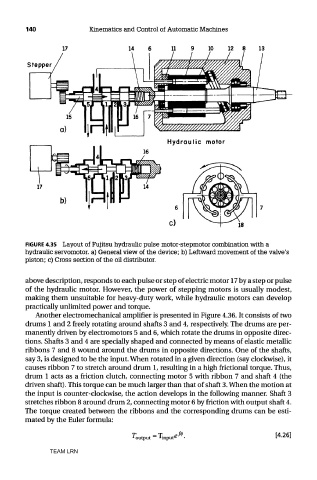
140               Kinematics and Control of Automatic Machines


        FIGURE 4.35 Layout of Fujitsu hydraulic pulse motor-stepmotor combination with a
        hydraulic servomotor, a) General view of the device; b) Leftward movement of the valve's
        piston; c) Cross section of the oil distributor.


        above description, responds to each pulse or step of electric motor 17 by a step or pulse
        of the hydraulic motor. However, the power of stepping motors is usually modest,
        making them unsuitable for heavy-duty work, while hydraulic motors can develop
        practically unlimited power and torque.
           Another electromechanical amplifier is presented in Figure 4.36. It consists of two
        drums 1 and 2 freely rotating around shafts 3 and 4, respectively. The drums are per-
        manently driven by electromotors 5 and 6, which rotate the drums in opposite direc-
        tions. Shafts 3 and 4 are specially shaped and connected by means of elastic metallic
        ribbons 7 and 8 wound around the drums in opposite directions. One of the shafts,
        say 3, is designed to be the input. When rotated in a given direction (say clockwise), it
        causes ribbon 7 to stretch around drum 1, resulting in a high frictional torque. Thus,
        drum 1 acts as a friction clutch, connecting motor 5 with ribbon 7 and shaft 4 (the
        driven shaft). This torque can be much larger than that of shaft 3. When the motion at
        the input is counter-clockwise, the action develops in the following manner. Shaft 3
        stretches ribbon 8 around drum 2, connecting motor 6 by friction with output shaft 4.
        The torque created between the ribbons and the corresponding drums can be esti-
        mated by the Euler formula:


               TEAM LRN