
Page 154 - Robot Builders Source Book - Gordon McComb
P. 154
142 Kinematics and Control of Automatic Machines
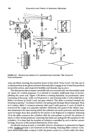
FIGURE 4.37 Mechanical readout for a punched-card controller. The Jacquard
loom mechanism.
warp are lifted, creating the required weave of the cloth. Those levers (10) that are in
a raised position at any given moment obviously fail to engage lever 12 and thus perform
no positive action, and respective heddles and threads stay in place.
Our discussion about master camshafts led us to consider the use of punched cards
(or tapes) for control purposes. It is natural to consider additional ways of accom-
plishing the same task. Figure 4.38 shows a rotating hydraulic (or pneumatic) valve
consisting of housing 1 with curved grooves 2, and rotating slider 3 with radial slot 4.
Slider 3 is driven by shaft 5 and, say, gear wheel 6. The slider is pressed towards the
housing by spring 7. To ensure rotation, the spring acts through thrust bearing 8. Thus
as it rotates, slider 3 connects pressure inlet port 9 with grooves 2, each of which is
connected by a pipe to a separate cylinder. Obviously, the speed of the slider's rota-
tion determines the time during which the cylinders are under pressure, and this time
must be longer than that needed for the piston to be displaced as required. (Opening
10 in the slider connects the cylinders with the atmosphere to permit the pistons to
return to their initial positions, assuming that there are springs for this purpose in the
cylinders.) It is clear that the number of cylinders controlled by such a device cannot
be large, because of the limited dimensions of the valve.
An electric analog of such a controller (electric distributor) is presented in Figure
4.39a). Arclike contacts 2 are fastened on the housing. Rotating slider contact 3 con-
TEAM LRN
nects these immovable contacts 2 with the power source in a certain order, the dura-