
Page 159 - Robot Builders Source Book - Gordon McComb
P. 159
4.3 Master Controller, Amplifiers 147
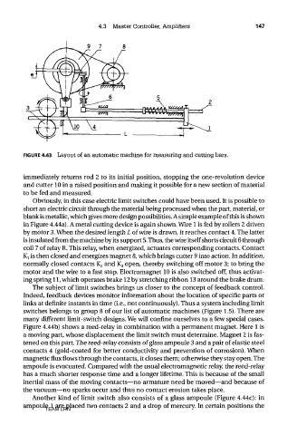
FIGURE 4.43 Layout of an automatic machine for measuring and cutting bars.
immediately returns rod 2 to its initial position, stopping the one-revolution device
and cutter 10 in a raised position and making it possible for a new section of material
to be fed and measured.
Obviously, in this case electric limit switches could have been used. It is possible to
short an electric circuit through the material being processed when the part, material, or
blank is metallic, which gives more design possibilities. A simple example of this is shown
in Figure 4.44a). A metal cutting device is again shown. Wire 1 is fed by rollers 2 driven
by motor 3. When the desired length L of wire is drawn, it reaches contact 4. The latter
is insulated from the machine by its support 5. Thus, the wire itself shorts circuit 6 through
coil 7 of relay R. This relay, when energized, actuates corresponding contacts. Contact
Kj is then closed and energizes magnet 8, which brings cutter 9 into action. In addition,
normally closed contacts K 2 and K 3 open, thereby switching off motor 3; to bring the
motor and the wire to a fast stop. Electromagnet 10 is also switched off, thus activat-
ing spring 11, which operates brake 12 by stretching ribbon 13 around the brake drum.
The subject of limit switches brings us closer to the concept of feedback control.
Indeed, feedback devices monitor information about the location of specific parts or
links at definite instants in time (i.e., not continuously). Thus a system including limit
switches belongs to group 8 of our list of automatic machines (Figure 1.5). There are
many different limit-switch designs. We will confine ourselves to a few special cases.
Figure 4.44b) shows a reed-relay in combination with a permanent magnet. Here 1 is
a moving part, whose displacement the limit switch must determine. Magnet 2 is fas-
tened on this part. The reed-relay consists of glass ampoule 3 and a pair of elastic steel
contacts 4 (gold-coated for better conductivity and prevention of corrosion). When
magnetic flux flows through the contacts, it closes them; otherwise they stay open. The
ampoule is evacuated. Compared with the usual electromagnetic relay, the reed-relay
has a much shorter response time and a longer lifetime. This is because of the small
inertial mass of the moving contacts—no armature need be moved—and because of
the vacuum—no sparks occur and thus no contact erosion takes place.
Another kind of limit switch also consists of a glass ampoule (Figure 4.44c): in
ampoule 1 are placed two contacts 2 and a drop of mercury. In certain positions the
TEAM LRN