
Page 163 - Robot Builders Source Book - Gordon McComb
P. 163
4.4 Dynamic Accuracy 151
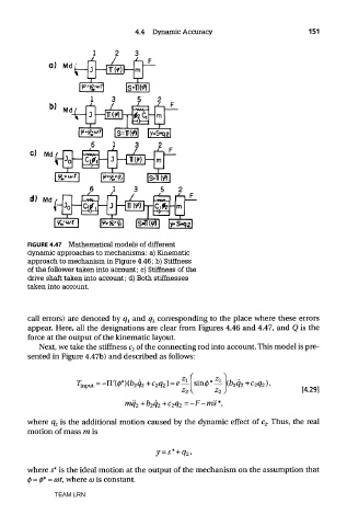
FIGURE 4.47 Mathematical models of different
dynamic approaches to mechanisms: a) Kinematic
approach to mechanism in Figure 4.46; b) Stiffness
of the follower taken into account; c) Stiffness of the
drive shaft taken into account; d) Both stiffnesses
taken into account.
call errors) are denoted by q l and q 2 corresponding to the place where these errors
appear. Here, all the designations are clear from Figures 4.46 and 4.47, and Q is the
force at the output of the kinematic layout.
Next, we take the stiffness c 2 of the connecting rod into account. This model is pre-
sented in Figure 4.47b) and described as follows:
where q 2 is the additional motion caused by the dynamic effect of c 2. Thus, the real
motion of mass ra is
where s* is the ideal motion at the output of the mechanism on the assumption that
0 = 0* = cot, where co is constant.
TEAM LRN