
Page 165 - Robot Builders Source Book - Gordon McComb
P. 165
4.4 Dynamic Accuracy 153
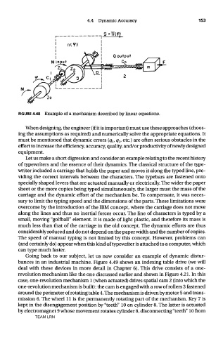
FIGURE 4.48 Example of a mechanism described by linear equations.
When designing, the engineer (if it is important) must use these approaches (choos-
ing the assumptions as required) and numerically solve the appropriate equations. It
must be mentioned that dynamic errors (q v q 2, etc.) are often serious obstacles in the
effort to increase the efficiency, accuracy, quality, and/or productivity of newly designed
equipment.
Let us make a short digression and consider an example relating to the recent history
of typewriters and the essence of their dynamics. The classical structure of the type-
writer included a carriage that holds the paper and moves it along the typed line, pro-
viding the correct intervals between the characters. The typebars are fastened onto
specially shaped levers that are actuated manually or electrically. The wider the paper
sheet or the more copies being typed simultaneously, the larger must the mass of the
carriage and the dynamic effort of the mechanism be. To compensate, it was neces-
sary to limit the typing speed and the dimensions of the parts. These limitations were
overcome by the introduction of the IBM concept, where the carriage does not move
along the lines and thus no inertia! forces occur. The line of characters is typed by a
small, moving "golfball" element. It is made of light plastic, and therefore its mass is
much less than that of the carriage in the old concept. The dynamic efforts are thus
considerably reduced and do not depend on the paper width and the number of copies.
The speed of manual typing is not limited by this concept. However, problems can
(and certainly do) appear when this kind of typewriter is attached to a computer, which
can type much faster.
Going back to our subject, let us now consider an example of dynamic distur-
bances in an industrial machine. Figure 4.49 shows an indexing table drive (we will
deal with these devices in more detail in Chapter 6). This drive consists of a one-
revolution mechanism like the one discussed earlier and shown in Figure 4.21. In this
case, one-revolution mechanism 1 (when actuated) drives spatial cam 2 (into which the
one-revolution mechanism is built): the cam is engaged with a row of rollers 3 fastened
around the perimeter of rotating table 4. The mechanism is driven by motor 5 and trans-
mission 6. The wheel 11 is the permanently rotating part of the mechanism. Key 7 is
kept in the disengagement position by "teeth" 10 on cylinder 8. The latter is actuated
by electromagnet 9 whose movement rotates cylinder 8, disconnecting "teeth" 10 from
TEAM LRN