
Page 170 - Robot Builders Source Book - Gordon McComb
P. 170
158 Kinematics and Control of Automatic Machines
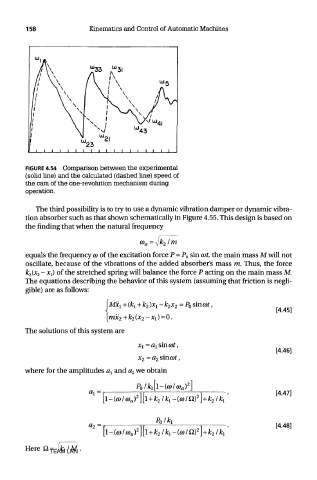
FIGURE 4.54 Comparison between the experimental
(solid line) and the calculated (dashed line) speed of
the cam of the one-revolution mechanism during
operation.
The third possibility is to try to use a dynamic vibration damper or dynamic vibra-
tion absorber such as that shown schematically in Figure 4.55. This design is based on
the finding that when the natural frequency
equals the frequency co of the excitation force P = P 0 sin cot, the main mass M will not
oscillate, because of the vibrations of the added absorber's mass m. Thus, the force
k 2(x 2 - xj of the stretched spring will balance the force P acting on the main mass M.
The equations describing the behavior of this system (assuming that friction is negli-
gible) are as follows:
The solutions of this system are
where for the amplitudes a\ and a 2 we obtain
TEAM LRN