
Page 172 - Robot Builders Source Book - Gordon McComb
P. 172
160 Kinematics and Control of Automatic Machines
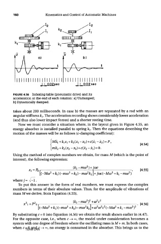
FIGURE 4.56 Indexing table (pneumatic drive) and its
acceleration at the end of each rotation: a) Undamped;
b) Dynamically damped.
takes about 200 milliseconds. In case b) the masses are separated by a rod with an
angular stiffness k 2. The acceleration recording shows considerably lower acceleration
(and thus also lower impact forces) and a shorter resting time.
Now we must consider a situation where, in the layout given in Figure 4.55, an
energy absorber is installed parallel to spring k 2. Then the equations describing the
motion of the masses will be as follows (c-damping coefficient):
Using the method of complex numbers we obtain, for mass M (which is the point of
interest), the following expression:
where 7= V-l.
To put this answer in the form of real numbers, we must express the complex
numbers in terms of their absolute values. Thus, for the amplitude of vibrations of
mass M we derive, from Equation (4.55),
By substituting c = 0 into Equation (4.56) we obtain the result shown earlier in (4.47).
For the opposite case, i.e., when c —»°°, the model under consideration becomes a
system with one degree of freedom where the oscillating mass is M+ m. In both cases,
when c = 0 and c -> °°, no energy is consumed in the absorber. This brings us to the
TEAM LRN