
Page 177 - Robot Builders Source Book - Gordon McComb
P. 177
4.6 Automatic Vibration Damping 165
FIGURE 4.61 Dynamically damped cam mechanism.
so that mass 4 on rods 5 will have the required parameters as a dynamic damper. The
disturbances (or errors) q change their frequency at different cam speeds; therefore,
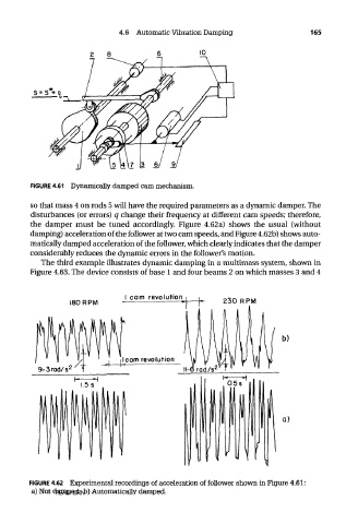
the damper must be tuned accordingly. Figure 4.62a) shows the usual (without
damping) acceleration of the follower at two cam speeds, and Figure 4.62b) shows auto-
matically damped acceleration of the follower, which clearly indicates that the damper
considerably reduces the dynamic errors in the follower's motion.
The third example illustrates dynamic damping in a multimass system, shown in
Figure 4.63. The device consists of base 1 and four beams 2 on which masses 3 and 4
FIGURE 4.62 Experimental recordings of acceleration of follower shown in Figure 4.61:
a) Not damped; b) Automatically damped.
TEAM LRN