
Page 175 - Robot Builders Source Book - Gordon McComb
P. 175
4.6 Automatic Vibration Damping 163
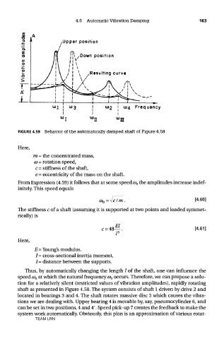
FIGURE 4.59 Behavior of the automatically damped shaft of Figure 4.58.
Here,
m = the concentrated mass,
CD = rotation speed,
c = stiffness of the shaft,
e = eccentricity of the mass on the shaft.
From Expression (4.59) it follows that at some speed CD O the amplitudes increase indef-
initely. This speed equals
The stiffness c of a shaft (assuming it is supported at two points and loaded symmet-
rically) is
Here,
E = Young's modulus,
/= cross-sectional inertia moment,
/ = distance between the supports.
Thus, by automatically changing the length / of the shaft, one can influence the
speed G) O at which the natural frequency a> 0 occurs. Therefore, we can propose a solu-
tion for a relatively silent (restricted values of vibration amplitudes), rapidly rotating
shaft as presented in Figure 4.58. The system consists of shaft 1 driven by drive 2 and
located in bearings 3 and 4. The shaft rotates massive disc 5 which causes the vibra-
tions we are dealing with. Upper bearing 4 is movable by, say, pneumocylinder 6, and
can be set in two positions, 4 and 4'. Speed pick-up 7 creates the feedback to make the
system work automatically. Obviously, this plan is an approximation of various rotat-
TEAM LRN