
Page 176 - Robot Builders Source Book - Gordon McComb
P. 176
164 Kinematics and Control of Automatic Machines
ing shafts with wheels, turbines, rotors, barrels, etc. Briefly, this automatic vibration-
restricting system operates as follows (see also Figure 4.59). When the shaft begins to
accelerate from zero speed, the upper bearing is in position 4' and the vibrational
amplitudes develop according to the dashed curve. After speed o^ is reached, the pick-
up gives a command to raise the bearing into position 4. Thus, the behavior of the
system is "switched" from the dashed curve to the solid curve, the resonance that would
occur at o> 3 (dashed curve) is avoided, and the amplitudes continue to develop along
the solid curve until the speed reaches <0 n. At this moment, the pick-up commands the
bearing to return to its initial position 4', thus avoiding the approach of the next crit-
ical situation at speed a> 2 while further acceleration develops along the broken curve
until speed CD IU, and so on. Decelerating the pick-up involves a similar series of com-
mands. Thus, the vibrational amplitudes never exceed the value A' (see Figure 4.59)
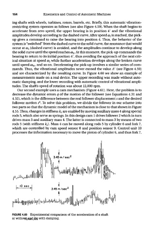
and are characterized by the resulting curve. In Figure 4.60 we show an example of
measurements made on a real device. The upper recording was made without auto-
matic damping, and the lower recording with automatic control of vibrational ampli-
tudes. The shaft's speed of rotation was about 12,000 rpm.
Our second example uses a cam mechanism (Figure 4.61). Here, the problem is to
decrease the dynamic errors q of the motion of the follower (see Equations 4.31 and
4.32), which is the difference between the real follower displacement 5 and the desired
follower motion s*. To solve this problem, we divide the follower in our scheme into
two parts so that the dynamic model of the mechanism is close to that shown in Figure
4.55. Thus, changes in stiffness k 2 are enabled by moving auxiliary mass 4 along special
rods 5, which also serve as springs. In this design cam 1 drives follower 2 which in turn
drives mass 3 and auxiliary mass 4. The latter is connected to mass 3 by means of two
rods 5 (with stiffness fc 2). Mass 4 can be moved along rods 5 by cylinder 6 and fork 7,
which are controlled by cam speed sensor 8 and position sensor 9. Control unit 10
processes the information necessary to move the piston of cylinder 6, and thus fork 7,
FIGURE 4.60 Experimental comparison of the acceleration of a shaft
a) without and (b) with damping.
TEAM LRN