
Page 169 - Robot Builders Source Book - Gordon McComb
P. 169
4.5 Damping of Harmful Vibrations 157
Here E is Young's modulus; /j and 1 2 are clear from Figure 4.52, and /j and 7 2 are iner-
tial moments of the cross-sections I and II, respectively.
The solution of the independent motion of the cam from Equation (4.37) is as
follows:
where n = b c/J c.
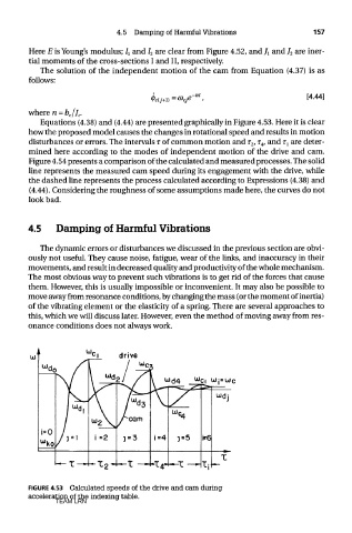
Equations (4.38) and (4.44) are presented graphically in Figure 4.53. Here it is clear
how the proposed model causes the changes in rotational speed and results in motion
disturbances or errors. The intervals r of common motion and T 2, r 4, and T I are deter-
mined here according to the modes of independent motion of the drive and cam.
Figure 4.54 presents a comparison of the calculated and measured processes. The solid
line represents the measured cam speed during its engagement with the drive, while
the dashed line represents the process calculated according to Expressions (4.38) and
(4.44). Considering the roughness of some assumptions made here, the curves do not
look bad.
4.5 Damping of Harmful Vibrations
The dynamic errors or disturbances we discussed in the previous section are obvi-
ously not useful. They cause noise, fatigue, wear of the links, and inaccuracy in their
movements, and result in decreased quality and productivity of the whole mechanism.
The most obvious way to prevent such vibrations is to get rid of the forces that cause
them. However, this is usually impossible or inconvenient. It may also be possible to
move away from resonance conditions, by changing the mass (or the moment of inertia)
of the vibrating element or the elasticity of a spring. There are several approaches to
this, which we will discuss later. However, even the method of moving away from res-
onance conditions does not always work.
FIGURE 4.53 Calculated speeds of the drive and cam during
acceleration of the indexing table.
TEAM LRN