
Page 158 - Robot Builders Source Book - Gordon McComb
P. 158
146 Kinematics and Control of Automatic Machines
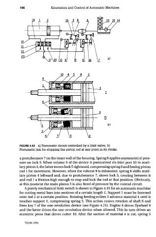
FIGURE 4.42 a) Pneumatic circuit controlled by a limit valve; b)
Pneumatic jam for stopping the piston rod at any point in its stroke.
a protuberance 7 on the inner wall of the housing. Spring 8 applies asymmetrical pres-
sure on lock 5. When volume 9 of the device is pressurized via inlet port 10 to auxil-
iary piston 4, the latter moves lock 5 rightward, compressing spring 8 and freeing piston
rod 1 for movement. However, when the volume 9 is exhausted, spring 8 shifts auxil-
iary piston 4 leftward and, due to protuberance 7, skews lock 5, creating between it
and rod 1 a friction high enough to stop and lock the rod at that position. Obviously,
at this moment the main piston 3 is also freed of pressure by the control circuit.
A purely mechanical limit switch is shown in Figure 4.43 for an automatic machine
for cutting metal bars into sections of a certain length L. Support 1 must be fastened
onto rod 2 at a certain position. Rotating feeding rollers 3 advance material 4 until it
touches support 1, compressing spring 5. This action causes rotation of shaft 6 and
frees key 7 of the one-revolution device (see Figure 4.21). Engine 8 drives flywheel 9
and the latter drives the one-revolution device when allowed. This in turn drives an
eccentric press that drives cutter 10. After the section of material 4 is cut, spring 5
TEAM LRN