
Page 124 - Robotics Designing the Mechanisms for Automated Machinery
P. 124
Exercises 113
Calculate the time needed to lift the mass (for both cases separately) from the
moment in time that the valve 3 is actuated until the time the mass reaches point s max.
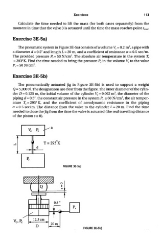
Exercise 3E-5a)
2
The pneumatic system in Figure 3E-5a) consists of a volume V c = 0.2 m , a pipe with
a diameter d = 0.5" and length L = 20 m, and a coefficient of resistance a = 0.5 sec/m.
2
The provided pressure P r= 50 N/cm . The absolute air temperature in the system T r
= 293° K. Find the time needed to bring the pressure P c in the volume V c to the value
2
P r = 50N/cm .
Exercise 3E-5b)
The pneumatically actuated jig in Figure 3E-5b) is used to support a weight
Q = 5,000 N. The designations are clear from the figure. The inner diameter of the cylin-
3
der D = 0.125 m, the initial volume of the cylinder V c = 0.002 m , the diameter of the
2
piping d = 0.5", the constant air pressure in the system P r = 60 N/cm , the air temper-
ature T c = 293° K, and the coefficient of aerodynamic resistance in the piping
a = 0.5 sec/m. The distance from the valve to the cylinder L = 20 m. Find the time
needed to close the jig from the time the valve is actuated (the real travelling distance
of the piston s = 0).
FIGURE 3E-5a)
FIGURE 3E-5b)