
Page 128 - Robotics Designing the Mechanisms for Automated Machinery
P. 128
4.1 Position Function 117
angular), we obtain an equation for the power on the driving and driven sides of the
mechanism (at this stage frictional losses of power can be neglected). Hence,
From Equation (4.2),
then
Obviously, H'(x) is the ratio between the driving and driven links. In the particular case
where the input motion can be considered uniform (i.e., x = constant and x = 0), it
follows, from Expression (4.3), that
The designer often has to deal with a chain of n mechanisms, for which
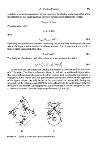
To illustrate this, let us take the Geneva mechanism as an example for calculation
of a n function. The diagram shown in Figure 4.1 will aid us in this task. It is obvious
that this mechanism can be analyzed only in motion, that is, when the driving link is
engaged with the driven one. For the four-slot Geneva cross shown on the right side
of the figure, this occurs only for 90° of the rotation of the driving link; during the
remainder of the rotation angle (270°) the driving link is idle. To avoid impact between
the links at the moment of engagement, the mechanism is usually designed so that,
at that very moment, there is a right angle between O tA and 0;A
FIGURE 4.1 Layout of a four-slot Geneva mechanism.