
Page 132 - Robotics Designing the Mechanisms for Automated Machinery
P. 132
4.1 Position Function 121
FIGURE 4.7 Modified Geneva mechanism.
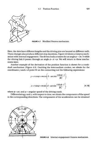
Here, the slots have different lengths and the driving pins are located on different radii.
These changes also produce different stop durations. Figure 4.8 shows a Geneva mech-
anism with internal engagement. The driven body a rotates for an angle iff = 2n /4 while
the driving link b passes through an angle <f> = n + i]/. We will return to these mecha-
nisms later.
Another example of the derivation of the position function is shown for a crank-
shaft mechanism (Figure 4.9). Omitting the intermediate strokes, we obtain for the
coordinates y and x of point M on the connecting rod the following expressions:
where 0 = cot, and CD = angular speed of the driving crank.
Differentiating y and x, with respect to time, we obtain the components of the speed
in the corresponding directions. The components of the acceleration can be obtained
FIGURE 4.8 Internal engagement Geneva mechanism.