
Page 130 - Robotics Designing the Mechanisms for Automated Machinery
P. 130
4.1 Position Function 119
When cfy/dt = a> 0 = constant, we obtain
For acceleration of the driven link we obtain
When 0 = a> Q we can simplify the expression to the form
and
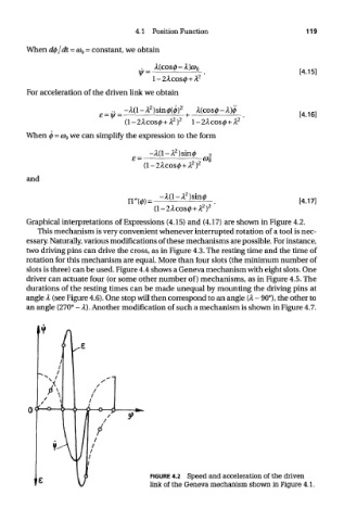
Graphical interpretations of Expressions (4.15) and (4.17) are shown in Figure 4.2.
This mechanism is very convenient whenever interrupted rotation of a tool is nec-
essary. Naturally, various modifications of these mechanisms are possible. For instance,
two driving pins can drive the cross, as in Figure 4.3. The resting time and the time of
rotation for this mechanism are equal. More than four slots (the minimum number of
slots is three) can be used. Figure 4.4 shows a Geneva mechanism with eight slots. One
driver can actuate four (or some other number of) mechanisms, as in Figure 4.5. The
durations of the resting times can be made unequal by mounting the driving pins at
angle A (see Figure 4.6). One stop will then correspond to an angle (A - 90°), the other to
an angle (270° - A). Another modification of such a mechanism is shown in Figure 4.7.
FIGURE 4.2 Speed and acceleration of the driven
link of the Geneva mechanism shown in Figure 4.1.