
Page 135 - Robotics Designing the Mechanisms for Automated Machinery
P. 135
124 Kinematics and Control of Automatic Machines
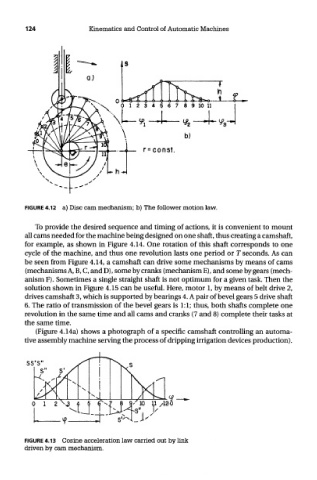
FIGURE 4.12 a) Disc cam mechanism; b) The follower motion law.
To provide the desired sequence and timing of actions, it is convenient to mount
all cams needed for the machine being designed on one shaft, thus creating a camshaft,
for example, as shown in Figure 4.14. One rotation of this shaft corresponds to one
cycle of the machine, and thus one revolution lasts one period or T seconds. As can
be seen from Figure 4.14, a camshaft can drive some mechanisms by means of cams
(mechanisms A, B, C, and D), some by cranks (mechanism E), and some by gears (mech-
anism F). Sometimes a single straight shaft is not optimum for a given task. Then the
solution shown in Figure 4.15 can be useful. Here, motor 1, by means of belt drive 2,
drives camshaft 3, which is supported by bearings 4. A pair of bevel gears 5 drive shaft
6. The ratio of transmission of the bevel gears is 1:1; thus, both shafts complete one
revolution in the same time and all cams and cranks (7 and 8) complete their tasks at
the same time.
(Figure 4.14a) shows a photograph of a specific camshaft controlling an automa-
tive assembly machine serving the process of dripping irrigation devices production).
FIGURE 4.13 Cosine acceleration law carried out by link
driven by cam mechanism.