
Page 138 - Robotics Designing the Mechanisms for Automated Machinery
P. 138
4.2 Camshafts 127
FIGURE 4.18 Flexible toothed rack for motion transmission.
choice of materials and coatings, so that the guide can be folded in various ways and
still provide satisfactory transmission of the motion.
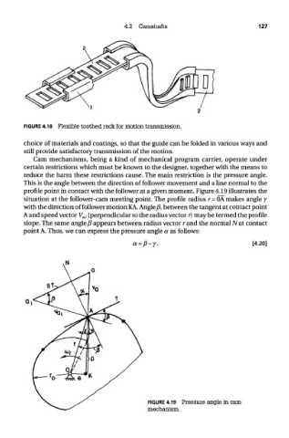
Cam mechanisms, being a kind of mechanical program carrier, operate under
certain restrictions which must be known to the designer, together with the means to
reduce the harm these restrictions cause. The main restriction is the pressure angle.
This is the angle between the direction of follower movement and a line normal to the
profile point in contact with the follower at a given moment. Figure 4.19 illustrates the
situation at the follower-cam meeting point. The profile radius r= OA makes angle j
with the direction of follower motion KA. Angle ft, between the tangent at contact point
A and speed vector V al (perpendicular to the radius vector r) may be termed the profile
slope. The same angle ft appears between radius vector r and the normal Nat contact
point A. Thus, we can express the pressure angle a as follows:
FIGURE 4.19 Pressure angle in cam
mechanism.