
Page 142 - Robotics Designing the Mechanisms for Automated Machinery
P. 142
4.2 Camshafts 131
into the connecting position, due to spring 5, when the slots of part 1 permit this. From
this moment on, parts 1 and 2 move together, as mentioned earlier. However, if, during
this first revolution, stop 4 returns to its previous position (cam III in Figure 4.20 ensures
this), then before the revolution is completed lever 3a meets the stop, rotates key 3
into the disconnecting position, and frees part 1 from part 2. Pins 6 restrict the angular
motion of the key. This kind of one-revolution mechanism has extensive applications.
At this point it is interesting to consider the problem of the flexibility of camshafts
and other mechanisms for carrying out position functions in hardware. Indeed, from
our description of the action of main and auxiliary camshafts, it would appear that, once
designed, manufactured, and assembled, these mechanisms cannot be changed. This
is, of course, true, and is completely adequate for "bang-bang" robotic systems (type
5 in Figure 1.5). However, there are ways of introducing some flexibility even into this
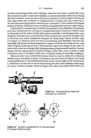
seemingly stiff, purely mechanical approach. Figure 4.22 shows the design of cam 1 and
shaft 2 together with special lock 3 which permits rapid cam change on the shaft. To
some extent, such cam change is like reprogramming a programmable machine. Another
design with the same purpose is shown in Figure 4.23a). Here, cam 1 is fixed on shaft
2 by means of nut 3. In Figure 4.23b) cam 1 is fixed by means of tooth-like coupling 2.
There are other ways in which the position function may be realized in a relatively
flexible way by mechanical means. For instance, the cam shown in Figure 4.24 is built
so that profile piece 2 can be fastened by bolts 3 and 4 at any angle on the circular base
1, which has a circular slot (it can be moved along this slot), thus yielding a wide range
of 5 values. Another example, shown in Figure 4.25, allows easy adjustment of the cam
FIGURE 4.22 Arrangement for rapid cam
exchange on a camshaft.
FIGURE 4.23 Another arrangement for a) Cam exchange;
b) Change of fixation angle.