
Page 145 - Robotics Designing the Mechanisms for Automated Machinery
P. 145
134 Kinematics and Control of Automatic Machines
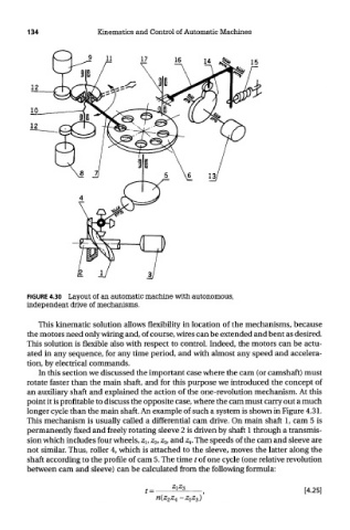
FIGURE 4.30 Layout of an automatic machine with autonomous,
independent drive of mechanisms.
This kinematic solution allows flexibility in location of the mechanisms, because
the motors need only wiring and, of course, wires can be extended and bent as desired.
This solution is flexible also with respect to control. Indeed, the motors can be actu-
ated in any sequence, for any time period, and with almost any speed and accelera-
tion, by electrical commands.
In this section we discussed the important case where the cam (or camshaft) must
rotate faster than the main shaft, and for this purpose we introduced the concept of
an auxiliary shaft and explained the action of the one-revolution mechanism. At this
point it is profitable to discuss the opposite case, where the cam must carry out a much
longer cycle than the main shaft. An example of such a system is shown in Figure 4.31.
This mechanism is usually called a differential cam drive. On main shaft 1, cam 5 is
permanently fixed and freely rotating sleeve 2 is driven by shaft 1 through a transmis-
sion which includes four wheels, z v z 2, z 3, and z 4. The speeds of the cam and sleeve are
not similar. Thus, roller 4, which is attached to the sleeve, moves the latter along the
shaft according to the profile of cam 5. The time t of one cycle (one relative revolution
between cam and sleeve) can be calculated from the following formula: