
Page 144 - Robotics Designing the Mechanisms for Automated Machinery
P. 144
4.2 Camshafts 133
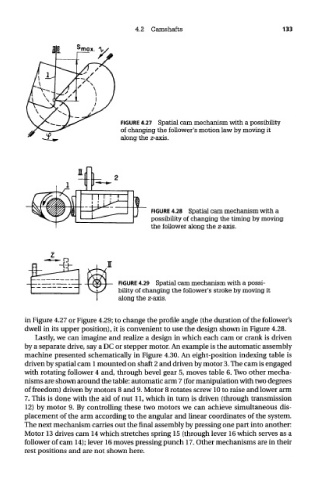
FIGURE 4.27 Spatial cam mechanism with a possibility
of changing the follower's motion law by moving it
along the z-axis.
FIGURE 4.28 Spatial cam mechanism with a
possibility of changing the timing by moving
the follower along the z-axis.
FIGURE 4.29 Spatial cam mechanism with a possi-
bility of changing the follower's stroke by moving it
along the z-axis.
in Figure 4.27 or Figure 4.29; to change the profile angle (the duration of the follower's
dwell in its upper position), it is convenient to use the design shown in Figure 4.28.
Lastly, we can imagine and realize a design in which each cam or crank is driven
by a separate drive, say a DC or stepper motor. An example is the automatic assembly
machine presented schematically in Figure 4.30. An eight-position indexing table is
driven by spatial cam 1 mounted on shaft 2 and driven by motor 3. The cam is engaged
with rotating follower 4 and, through bevel gear 5, moves table 6. Two other mecha-
nisms are shown around the table: automatic arm 7 (for manipulation with two degrees
of freedom) driven by motors 8 and 9. Motor 8 rotates screw 10 to raise and lower arm
7. This is done with the aid of nut 11, which in turn is driven (through transmission
12) by motor 9. By controlling these two motors we can achieve simultaneous dis-
placement of the arm according to the angular and linear coordinates of the system.
The next mechanism carries out the final assembly by pressing one part into another:
Motor 13 drives cam 14 which stretches spring 15 (through lever 16 which serves as a
follower of cam 14); lever 16 moves pressing punch 17. Other mechanisms are in their
rest positions and are not shown here.