
Page 150 - Robotics Designing the Mechanisms for Automated Machinery
P. 150
138 Kinematics and Control of Automatic Machines
Analogously, a pneumatic readout system can be devised. Figure 4.33b) shows a
diagram of a pneumatic readout device that can work with either vacuum or pressure.
Perforated card 2 is placed on base 1 and is sealed by hollow clamp 3. The clamp is
connected to a pressure or vacuum source so that pressure or vacuum is transmitted
through the openings in the card to the piping system. Here, the readout of the device
is a combination of pressures or vacuums.
The fastest readout device is based on photoelectric sensors, a scheme of which is
shown in Figure 4.33c). This device consists of base 1 on which punched card 2 is
placed. The perforated card is exposed to light source 3. Thus, those photosensors 4
that are protected by the card are not actuated, while those exposed to light entering
the perforations in the card are actuated, yielding a combination of electrical con-
nections in the output wiring. The high speed of response of photoelectric devices
makes it possible to use continuously running perforated tapes, as opposed to the
devices discussed earlier, which require discontinuous (discrete) reading of informa-
tion because of their slow response. Some electrical devices constitute an exception
to this rule. However, the pressure of contacts sliding along the tape causes significant
wear of the tape and the contacts, and therefore discontinuous readouts are prefer-
able. This is not to mention the lower speed of the tape (because of the time response)
than in photoelectric devices. The latter devices also have the advantage of no mechan-
ical contact, so that wear due to friction does not occur. Mechanical readout devices
for perforated cards will be discussed after amplifiers are considered. (A combination
of such a readout with a purely mechanical amplifier will be shown in Figure 4.37.)
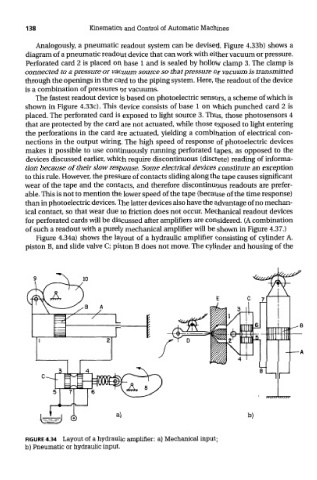
Figure 4.34a) shows the layout of a hydraulic amplifier consisting of cylinder A.
piston B, and slide valve C; piston B does not move. The cylinder and housing of the
FIGURE 4.34 Layout of a hydraulic amplifier: a) Mechanical input;
b) Pneumatic or hydraulic input.