
Page 151 - Robotics Designing the Mechanisms for Automated Machinery
P. 151
4.3 Master Controller, Amplifiers 139
valve are made as one unit. Thus, when for some reason the piston of the valve is dis-
placed (leftwards, say), the pressure from port 7 passes through outlet 3 to cylinder
port 1, while in this situation the idle volume of the cylinder is connected to outlet 6
and liquid tank through its outlet 2 and port 4 of the valve. The pressure entering the
left volume of the cylinder causes a leftward movement and equivalent displacement
of the slide valve housing. The movement of this housing relative to the valve piston
closes all ports and therefore stops the cylinder. To continue the movement of the cylin-
der, the valve piston must again be displaced leftward, and so on. To reverse the motion
of the cylinder, the piston of the valve must be moved rightward; ports 7,4, and 2 then
connect and the right volume of the cylinder is under pressure, while the liquid is freed
to flow into the tank through ports 1, 3, and 5. The valve's piston can be moved by a
cam 8 and thus the cylinder will almost copy the cam profile. This is a good way of
making a tracer: as the gauge fastened to the valve piston rod follows, say, a wooden
model, the cylinder drives a milling head which processes a metal blank 10.
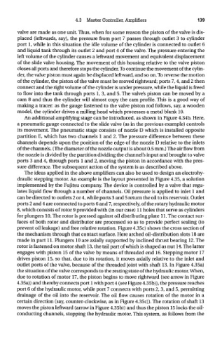
An additional amplifying stage can be introduced, as shown in Figure 4.34b. Here,
a pneumatic gauge connected to the slide valve (as in the previous example) controls
its movement. The pneumatic stage consists of nozzle D which is installed opposite
partition E, which has two channels 1 and 2. The pressure difference between these
channels depends upon the position of the edge of the nozzle D relative to the inlets
of the channels. (The diameter of the nozzle output is about 0.5 mm.) The air flow from
the nozzle is divided by the partition dividing the channel's input and brought to valve
ports 3 and 4, through ports 1 and 2, moving the piston in accordance with the pres-
sure difference. The subsequent action of the system is as described above.
The ideas applied in the above amplifiers can also be used to design an electrohy-
draulic stepping motor. An example is the layout presented in Figure 4.35, a solution
implemented by the Fujitsu company. The device is controlled by a valve that regu-
lates liquid flow through a number of channels. Oil pressure is applied to inlet 1 and
can be directed to outlets 2 or 4, while ports 3 and 5 return the oil to its reservoir. Outlet
ports 2 and 4 are connected to ports 6 and 7, respectively, of the rotary hydraulic motor
8, which consists of rotor 9 provided with (in our case) 11 holes that serve as cylinders
for plungers 10. The rotor is pressed against oil distributing plate 11. The contact sur-
faces of both rotor and distributor are processed so as to provide perfect sealing (to
prevent oil leakage) and free relative rotation. Figure 4.35c) shows the cross section of
the mechanism through that contact surface. Here arched oil-distribution slots 18 are
made in part 11. Plungers 10 are axially supported by inclined thrust bearing 12. The
rotor is fastened on motor shaft 13, the tail part of which is shaped as nut 14. The latter
engages with piston 15 of the valve by means of threaded end 16. Stepping motor 17
drives piston 15, so that, due to its rotation, it moves axially relative to the inlet and
outlet ports of the valve, because of the threaded joint with shaft 13. In Figure 4.35a)
the situation of the valve corresponds to the resting state of the hydraulic motor. When,
due to rotation of motor 17, the piston begins to move rightward (see arrow in Figure
4.35a)) and thereby connects port 1 with port 4 (see Figure 4.35b)), the pressure reaches
port 6 of the hydraulic motor, while port 7 connects with ports 2, 3, and 5, permitting
drainage of the oil into the reservoir. The oil flow causes rotation of the motor in a
certain direction (say, counter-clockwise, as in Figure 4.35c)). The rotation of shaft 13
moves the piston leftward (arrow in Figure 4.35b)) and thus the piston 15 locks the oil-
conducting channels, stopping the hydraulic motor. This system, as follows from the