
Page 156 - Robotics Designing the Mechanisms for Automated Machinery
P. 156
144 Kinematics and Control of Automatic Machines
tion of these connections obviously depending on the arc lengths. This device can, for
instance, actuate electromagnetic valves.
We should also mention the electromagnetic relay. Originally devised for amplify-
ing current in the first telegraph lines, it has found wide use in the automation of
machines and tools. The structure and action of this device, shown in Figure 4.39b, is
as follows. Core 1 also serves as a base and holds coil 2. Armature 3 has the form of an
angular lever. One arm of this lever actuates a group of electric contacts 4. Sometimes
a spring 5 is used to keep the armature at a certain distance from the core. When ener-
gized, the coil induces a magnetic flux and the armature overpowers the spring, closing
the gap and simultaneously actuating the contacts. In the general case, some of the
contacts can be normally open while the others are normally closed. Thus, when the
coil is energized the contacts change their state: the normally opened contacts close
and the normally closed contacts open. The power needed for energizing the coil is
much smaller than that controlled by the contacts. This kind of amplifier belongs to
the so-called "on-off" kind.
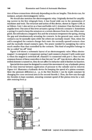
Figure 4.40 shows a schematic layout of an electromagnetic valve. When electro-
magnet 1 is energized, it compresses spring 2 and connects channel 3 with outlet port
4; when the magnet is switched off, channel 3 is connected with port 5. Here too the
common feature of these controllers is that they are "on-off" type devices; after the con-
trolled element is turned on, they do not affect its behavior until it finishes its function.
Special devices must be designed to control the movement of, say, a hydraulic piston
in the time interval between application of pressure to the cylinder and its removal.
Figure 4.41 illustrates a hydraulic device for keeping the speed of a piston constant.
Here the pressure difference p^ - p 2 in the first throttle 1 can be made constant by
changing the cross-sectional area in the second throttle 2. Thus, the flow rate through
the throttles is kept constant, ensuring constant speed of the piston even for a vari-
able resisting force p.
FIGURE 4.40 Layout of an electromagnetic valve.