
Page 157 - Robotics Designing the Mechanisms for Automated Machinery
P. 157
4.3 Master Controller, Amplifiers 145
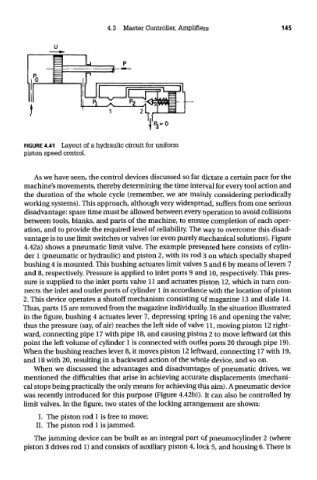
FIGURE 4.41 Layout of a hydraulic circuit for uniform
piston speed control.
As we have seen, the control devices discussed so far dictate a certain pace for the
machine's movements, thereby determining the time interval for every tool action and
the duration of the whole cycle (remember, we are mainly considering periodically
working systems). This approach, although very widespread, suffers from one serious
disadvantage: spare time must be allowed between every operation to avoid collisions
between tools, blanks, and parts of the machine, to ensure completion of each oper-
ation, and to provide the required level of reliability. The way to overcome this disad-
vantage is to use limit switches or valves (or even purely mechanical solutions). Figure
4.42a) shows a pneumatic limit valve. The example presented here consists of cylin-
der 1 (pneumatic or hydraulic) and piston 2, with its rod 3 on which specially shaped
bushing 4 is mounted. This bushing actuates limit valves 5 and 6 by means of levers 7
and 8, respectively. Pressure is applied to inlet ports 9 and 10, respectively. This pres-
sure is supplied to the inlet ports valve 11 and actuates piston 12, which in turn con-
nects the inlet and outlet ports of cylinder 1 in accordance with the location of piston
2. This device operates a shutoff mechanism consisting of magazine 13 and slide 14.
Thus, parts 15 are removed from the magazine individually. In the situation illustrated
in the figure, bushing 4 actuates lever 7, depressing spring 16 and opening the valve;
thus the pressure (say, of air) reaches the left side of valve 11, moving piston 12 right-
ward, connecting pipe 17 with pipe 18, and causing piston 2 to move leftward (at this
point the left volume of cylinder 1 is connected with outlet ports 20 through pipe 19).
When the bushing reaches lever 8, it moves piston 12 leftward, connecting 17 with 19,
and 18 with 20, resulting in a backward action of the whole device, and so on.
When we discussed the advantages and disadvantages of pneumatic drives, we
mentioned the difficulties that arise in achieving accurate displacements (mechani-
cal stops being practically the only means for achieving this aim). A pneumatic device
was recently introduced for this purpose (Figure 4.42b)). It can also be controlled by
limit valves. In the figure, two states of the locking arrangement are shown:
I. The piston rod 1 is free to move;
II. The piston rod 1 is jammed.
The jamming device can be built as an integral part of pneumocylinder 2 (where
piston 3 drives rod 1) and consists of auxiliary piston 4, lock 5, and housing 6. There is