
Page 162 - Robotics Designing the Mechanisms for Automated Machinery
P. 162
150 Kinematics and Control of Automatic Machines
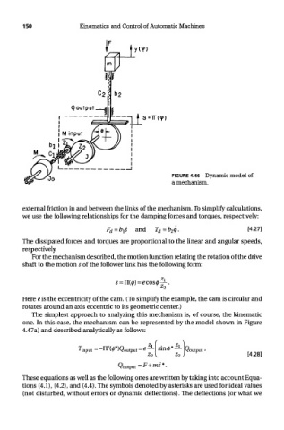
FIGURE 4.46 Dynamic model of
a mechanism.
external friction in and between the links of the mechanism. To simplify calculations,
we use the following relationships for the damping forces and torques, respectively:
The dissipated forces and torques are proportional to the linear and angular speeds,
respectively.
For the mechanism described, the motion function relating the rotation of the drive
shaft to the motion 5 of the follower link has the following form:
Here e is the eccentricity of the cam. (To simplify the example, the cam is circular and
rotates around an axis eccentric to its geometric center.)
The simplest approach to analyzing this mechanism is, of course, the kinematic
one. In this case, the mechanism can be represented by the model shown in Figure
4.47a) and described analytically as follows:
These equations as well as the following ones are written by taking into account Equa-
tions (4.1), (4.2), and (4.4). The symbols denoted by asterisks are used for ideal values
(not disturbed, without errors or dynamic deflections). The deflections (or what we