
Page 164 - Robotics Designing the Mechanisms for Automated Machinery
P. 164
152 Kinematics and Control of Automatic Machines
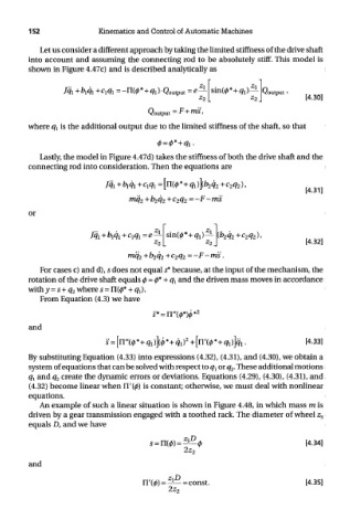
Let us consider a different approach by taking the limited stiffness of the drive shaft
into account and assuming the connecting rod to be absolutely stiff. This model is
shown in Figure 4.47c) and is described analytically as
where q t is the additional output due to the limited stiffness of the shaft, so that
Lastly, the model in Figure 4.47d) takes the stiffness of both the drive shaft and the
connecting rod into consideration. Then the equations are
or
For cases c) and d), s does not equal s* because, at the input of the mechanism, the
rotation of the drive shaft equals 0 = 0* + q l and the driven mass moves in accordance
with y = s + q 2 where 5 = n(0* + qj.
From Equation (4.3) we have
and
By substituting Equation (4.33) into expressions (4.32), (4.31), and (4.30), we obtain a
system of equations that can be solved with respect to q l or q 2. These additional motions
q l and q 2 create the dynamic errors or deviations. Equations (4.29), (4.30), (4.31), and
(4.32) become linear when IT(0) is constant; otherwise, we must deal with nonlinear
equations.
An example of such a linear situation is shown in Figure 4.48, in which mass m is
driven by a gear transmission engaged with a toothed rack. The diameter of wheel z^
equals D, and we have
and