
Page 167 - Robotics Designing the Mechanisms for Automated Machinery
P. 167
4.4 Dynamic Accuracy 155
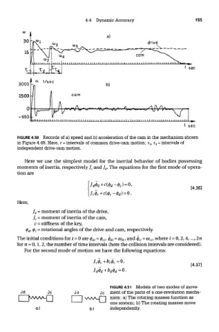
FIGURE 4.50 Records of a) speed and b) acceleration of the cam in the mechanism shown
in Figure 4.49. Here, T = intervals of common drive-cam motion; T 2, T 4 = intervals of
independent drive-cam motion.
Here we use the simplest model for the inertial behavior of bodies possessing
moments of inertia, respectively J c and/ rf. The equations for the first mode of opera-
Here,
The initial conditions for t= 0 are <j) di = <p ci, § di = co di, and <j) ci = a> ci, where / = 0,2,4,..., 2n
for n = 0,1,2, the number of time intervals (here the collision intervals are considered).
For the second mode of motion we have the following equations:
FIGURE 4.51 Models of two modes of move-
ment of the parts of a one-revolution mecha-
nism: a) The rotating masses function as
one system; b) The rotating masses move
independently.