
Page 172 - Robotics Designing the Mechanisms for Automated Machinery
P. 172
160 Kinematics and Control of Automatic Machines
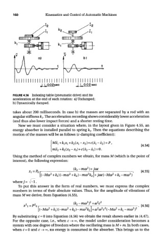
FIGURE 4.56 Indexing table (pneumatic drive) and its
acceleration at the end of each rotation: a) Undamped;
b) Dynamically damped.
takes about 200 milliseconds. In case b) the masses are separated by a rod with an
angular stiffness k 2. The acceleration recording shows considerably lower acceleration
(and thus also lower impact forces) and a shorter resting time.
Now we must consider a situation where, in the layout given in Figure 4.55, an
energy absorber is installed parallel to spring k 2. Then the equations describing the
motion of the masses will be as follows (c-damping coefficient):
Using the method of complex numbers we obtain, for mass M (which is the point of
interest), the following expression:
where 7= V-l.
To put this answer in the form of real numbers, we must express the complex
numbers in terms of their absolute values. Thus, for the amplitude of vibrations of
mass M we derive, from Equation (4.55),
By substituting c = 0 into Equation (4.56) we obtain the result shown earlier in (4.47).
For the opposite case, i.e., when c —»°°, the model under consideration becomes a
system with one degree of freedom where the oscillating mass is M+ m. In both cases,
when c = 0 and c -> °°, no energy is consumed in the absorber. This brings us to the