
Page 166 - Robotics Designing the Mechanisms for Automated Machinery
P. 166
154 Kinematics and Control of Automatic Machines
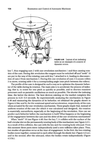
FIGURE 4.49 Layout of an indexing
table as an example of a source of
dynamic errors.
key 7, thus engaging cam 2 with one-revolution mechanism 1 and thus causing rota-
tion of the cam. During this revolution the magnet must be switched off and "teeth" 10
are put in the way of the rotating cam with key 7 attached to it, leading to disconnec-
tion of cam 2 from mechanism 1. During this one revolution of cam 2 it causes rollers
3 to move, rotating table 4 for a corresponding angle (one pitch between the rollers).
The profile of the cam is designed in such a way as to optimize the dynamic behav-
ior of the table during its rotation. The main aim is to accelerate the process of index-
ing; that is, to rotate for one pitch as quickly as possible, and to shorten transient
processes such as parasitic oscillations as much as possible. The shorter the indexing
time, the better the device. The best devices existing on the market complete this
process in 0.25-0.3 seconds. By experimentally analyzing the mechanism in Figure
4.49 and measuring the dynamics of its behavior, we obtained the graphs shown in
Figure 4.50a) and b), for the rotational speed and acceleration, respectively, of the cam
when actuated by the one-revolution mechanism. These graphs imply that, instead of
uniform rotation of the cam (for which it was calculated and designed), the rotation
is essentially nonuniform, especially at the beginning of the revolution. How can we
predict such behavior before the mechanism is built? What happens at the beginning
of the engagement between the cam and the drive of the one-revolution mechanism?
When "teeth" 10 (see Figure 4.49) free the key 7, it collides with the surface of the
half-circular slot on the permanently rotating body of the mechanism (see Figure 4.21).
As a result of this collision, the cam with the key and the rotating body rebound. From
this moment these parts move independently until a new collision takes place. Thus,
two modes of operation occur at the time of engagement. In the first, the two rotating
bodies move together, connected to each other through the elastic key (Figure 4.51a));
and in the second, after the rebound, when the bodies rotate independently (Figure
4.51b)).