
Page 134 - Robotics Designing the Mechanisms for Automated Machinery
P. 134
4.2 Camshafts 123
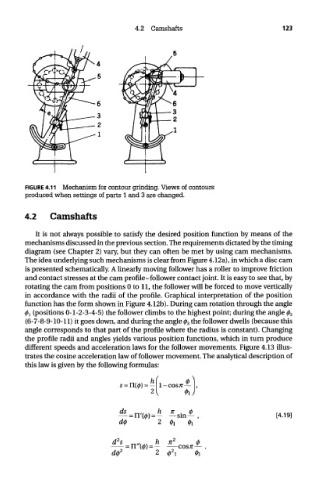
FIGURE 4.11 Mechanism for contour grinding. Views of contours
produced when settings of parts 1 and 3 are changed.
4.2 Camshafts
It is not always possible to satisfy the desired position function by means of the
mechanisms discussed in the previous section. The requirements dictated by the timing
diagram (see Chapter 2) vary, but they can often be met by using cam mechanisms.
The idea underlying such mechanisms is clear from Figure 4.12a), in which a disc cam
is presented schematically. A linearly moving follower has a roller to improve friction
and contact stresses at the cam profile-follower contact joint. It is easy to see that, by
rotating the cam from positions 0 to 11, the follower will be forced to move vertically
in accordance with the radii of the profile. Graphical interpretation of the position
function has the form shown in Figure 4.12b). During cam rotation through the angle
0! (positions 0-1-2-3-4-5) the follower climbs to the highest point; during the angle 0 2
(6-7-8-9-10-11) it goes down, and during the angle 0 3 the follower dwells (because this
angle corresponds to that part of the profile where the radius is constant). Changing
the profile radii and angles yields various position functions, which in turn produce
different speeds and acceleration laws for the follower movements. Figure 4.13 illus-
trates the cosine acceleration law of follower movement. The analytical description of
this law is given by the following formulas: