
Page 183 - Robotics Designing the Mechanisms for Automated Machinery
P. 183
4.7 Electrically Controlled Vibration Dampers 171
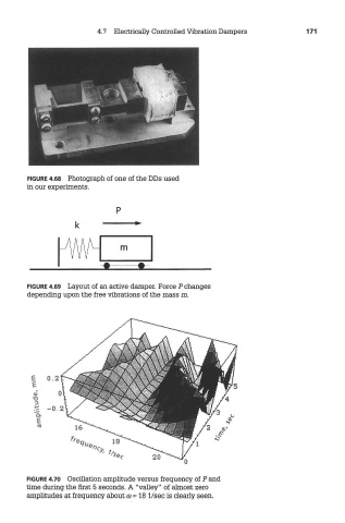
FIGURE 4.68 Photograph of one of the DDs used
in our experiments.
FIGURE 4.69 Layout of an active damper. Force P changes
depending upon the free vibrations of the mass m.
FIGURE 4.70 Oscillation amplitude versus frequency of P and
time during the first 5 seconds. A "valley" of almost zero
amplitudes at freo^iency about co = 18 I/sec is clearly seen.