
Page 40 - Robotics Designing the Mechanisms for Automated Machinery
P. 40
1.5 Nonindustrial Representatives of the Robot Family 29
movements of the internal layer and is responsible for amplifying the forces. This kind
of system was first used in about 1960 in the Cornell Aeronautical Laboratory, U.S.A.
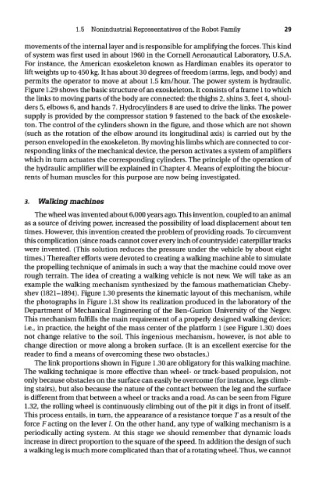
For instance, the American exoskeleton known as Hardiman enables its operator to
lift weights up to 450 kg. It has about 30 degrees of freedom (arms, legs, and body) and
permits the operator to move at about 1.5 km/hour. The power system is hydraulic.
Figure 1.29 shows the basic structure of an exoskeleton. It consists of a frame 1 to which
the links to moving parts of the body are connected: the thighs 2, shins 3, feet 4, shoul-
ders 5, elbows 6, and hands 7. Hydrocylinders 8 are used to drive the links. The power
supply is provided by the compressor station 9 fastened to the back of the exoskele-
ton. The control of the cylinders shown in the figure, and those which are not shown
(such as the rotation of the elbow around its longitudinal axis) is carried out by the
person enveloped in the exoskeleton. By moving his limbs which are connected to cor-
responding links of the mechanical device, the person activates a system of amplifiers
which in turn actuates the corresponding cylinders. The principle of the operation of
the hydraulic amplifier will be explained in Chapter 4. Means of exploiting the biocur-
rents of human muscles for this purpose are now being investigated.
3. Walking machines
The wheel was invented about 6,000 years ago. This invention, coupled to an animal
as a source of driving power, increased the possibility of load displacement about ten
times. However, this invention created the problem of providing roads. To circumvent
this complication (since roads cannot cover every inch of countryside) caterpillar tracks
were invented. (This solution reduces the pressure under the vehicle by about eight
times.) Thereafter efforts were devoted to creating a walking machine able to simulate
the propelling technique of animals in such a way that the machine could move over
rough terrain. The idea of creating a walking vehicle is not new. We will take as an
example the walking mechanism synthesized by the famous mathematician Cheby-
shev (1821-1894). Figure 1.30 presents the kinematic layout of this mechanism, while
the photographs in Figure 1.31 show its realization produced in the laboratory of the
Department of Mechanical Engineering of the Ben-Gurion University of the Negev.
This mechanism fulfills the main requirement of a properly designed walking device;
i.e., in practice, the height of the mass center of the platform 1 (see Figure 1.30) does
not change relative to the soil. This ingenious mechanism, however, is not able to
change direction or move along a broken surface. (It is an excellent exercise for the
reader to find a means of overcoming these two obstacles.)
The link proportions shown in Figure 1.30 are obligatory for this walking machine.
The walking technique is more effective than wheel- or track-based propulsion, not
only because obstacles on the surface can easily be overcome (for instance, legs climb-
ing stairs), but also because the nature of the contact between the leg and the surface
is different from that between a wheel or tracks and a road. As can be seen from Figure
1.32, the rolling wheel is continuously climbing out of the pit it digs in front of itself.
This process entails, in turn, the appearance of a resistance torque Tas a result of the
force F acting on the lever /. On the other hand, any type of walking mechanism is a
periodically acting system. At this stage we should remember that dynamic loads
increase in direct proportion to the square of the speed. In addition the design of such
a walking leg is much more complicated than that of a rotating wheel. Thus, we cannot