
Page 71 - Robotics Designing the Mechanisms for Automated Machinery
P. 71
60 Concepts and Layouts
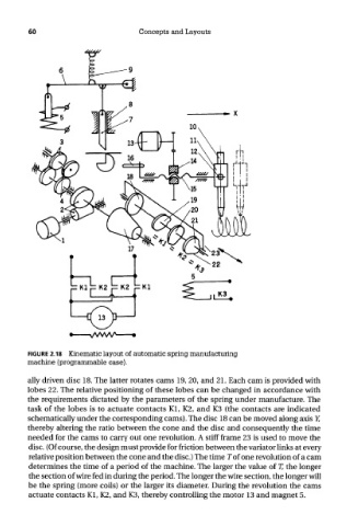
FIGURE 2.18 Kinematic layout of automatic spring manufacturing
machine (programmable case).
ally driven disc 18. The latter rotates cams 19, 20, and 21. Each cam is provided with
lobes 22. The relative positioning of these lobes can be changed in accordance with
the requirements dictated by the parameters of the spring under manufacture. The
task of the lobes is to actuate contacts Kl, K2, and K3 (the contacts are indicated
schematically under the corresponding cams). The disc 18 can be moved along axis Y,
thereby altering the ratio between the cone and the disc and consequently the time
needed for the cams to carry out one revolution. A stiff frame 23 is used to move the
disc. (Of course, the design must provide for friction between the variator links at every
relative position between the cone and the disc.) The time T of one revolution of a cam
determines the time of a period of the machine. The larger the value of T, the longer
the section of wire fed in during the period. The longer the wire section, the longer will
be the spring (more coils) or the larger its diameter. During the revolution the cams
actuate contacts Kl, K2, and K3, thereby controlling the motor 13 and magnet 5.