
Page 76 - Robotics Designing the Mechanisms for Automated Machinery
P. 76
3.1 Mechanically Driven Bodies 65
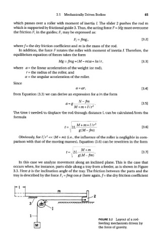
which passes over a roller with moment of inertia /. The slider 2 pushes the rod m
which is supported by frictional guide 3. Thus, the acting force F=Mg must overcome
the friction F { in the guides; F l may be expressed as:
where/= the dry friction coefficient and m is the mass of the rod.
In addition, the force F rotates the roller with moment of inertia /. Therefore, the
equilibrium equation of forces takes the form
where a = the linear acceleration of the weight (or rod),
r = the radius of the roller, and
a = the angular acceleration of the roller.
Since
from Equation (3.3) we can derive an expression for a in the form
The time t needed to displace the rod through distance L can be calculated from the
formula
2
Obviously, for I/r « (M+ m) (i.e., the influence of the roller is negligible in com-
parison with that of the moving masses), Equation (3.6) can be rewritten in the form
In this case we analyze movement along an inclined plane. This is the case that
occurs when, for instance, parts slide along a tray from a feeder, as is shown in Figure
3.3. Here <j) is the inclination angle of the tray. The friction between the parts and the
tray is described by the force F l =frng cos 0 (here again, /= the dry friction coefficient
FIGURE 3.2 Layout of a rod-
feeding mechanism driven by
the force of gravity.