
Page 134 - Robots Androids and Animatrons : 12 Incredible Projects You Can Build
P. 134
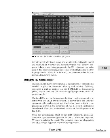
6.14 Hex file loaded into EPIC program


                                       the microcontroller is not blank, you are given the options to cancel
                                       the operation or overwrite the existing program with the new pro-
                                       gram. If there is an existing program in the PIC chip’s memory, write  113
                                       over it. The machine language code lines are highlighted as the PIC
                                       is  programmed.  When  it  is  finished,  the  microcontroller  is  pro-
                                       grammed and ready to run.
                               Testing the PIC microcontroller

                                       The schematic shows how minimal is the number of components
                                       needed  to  get  your  microcontroller  up  and  running.  Primarily
                                       you  need  a  pull-up  resistor  on  pin  4  (MCLR),  a  4-megahertz
                                       (MHz) crystal with two [22-picofarad (pF)] capacitors, and a 5V
                                       power supply.
                                       The two LEDs and the two current-limiting resistors connected in
                                       series with the LEDs are the output. It allows us to see that the
                                       microcontroller and program are functioning. Assemble the com-
                                       ponents as shown in the schematic of Fig. 6.15 on the solderless
                                       breadboard. When you are finished, your work should appear as in
                                       Fig. 6.16.

                                       While the specifications sheet on the 16F84 states the microcon-
                                       troller will operate on voltages from 2V to 6V, I provided a regulated
                                       5V power supply for the circuit. The regulated power supply consists
                                       of a 7805 voltage regulator and two filter capacitors.


                                                       Team LRN                                      Intelligence