
Page 143 - Robots Androids and Animatrons : 12 Incredible Projects You Can Build
P. 143
The program for the PICBASIC compiler is as follows:
‘PICBASIC Compiler
‘REM test switch high
input 4 ‘Set pin RB4 to read switch
start:
if pin4 1 then blink ‘If switch is high, then blink LED
goto start ‘If not, check switch again
blink: ‘Blink routine
high 0 ‘Bring RB0 high to light LED
1
pause 250 ‘Wait second
4
low 0 ‘Bring RB0 low to turn off LED
1
pause 250 ‘Wait second
4
goto start ‘Check switch again
The program for the PICBASIC Pro compiler is as follows:
‘PICBASIC Compiler Pro
‘REM test switch high
input portb.4 ‘Set pin RB4 to read switch
start:
if portb.4 1 then blink ‘If switch is high, then blink LED
goto start ‘If not, check again
122 blink: ‘Blink LED routine
high 0 ‘Bring RB0 high to light LED
1
pause 250 ‘Wait second
4
low 0 ‘Bring RB0 low to turn off LED
1
pause 250 ‘Wait second
4
goto start ‘Check switch again
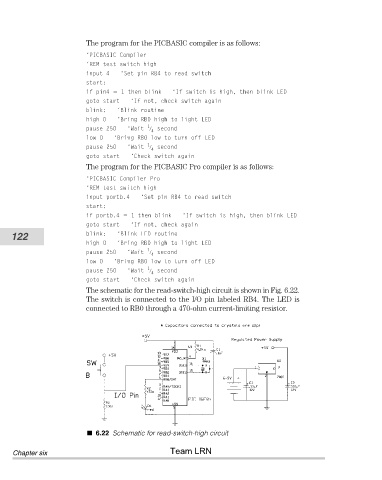
The schematic for the read-switch-high circuit is shown in Fig. 6.22.
The switch is connected to the I/O pin labeled RB4. The LED is
connected to RB0 through a 470-ohm current-limiting resistor.
6.22 Schematic for read-switch-high circuit
Team LRN
Chapter six